4
Installation
Rack setup and assembly of the pads and pedals are described in detail in the enclosed set
assembly guide. Finally check that all cables between the pads and the drum module have
been properly connected.
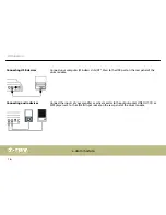
Connect the supplied D-sub plug of the pad connector cable to the D-sub input socket on the
rear panel of the drum module.
Connect the included power supply unit to the POWER input on the rear panel of the drum
module and then put the power plug into the power outlet.
Rack setup, connecting pads
and pedals
Connecting the pads
Connecting the power adapter
Installation
MPS-500 USB
15
Summary of Contents for MPS-500 USB
Page 1: ...MPS 500 USB e drum module user manual...
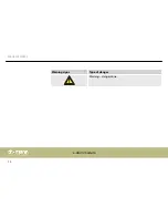
Page 10: ...Warning signs Type of danger Warning danger zone General notes e drum module 10...
Page 18: ...5 Operating elements Front panel Operating elements e drum module 18...
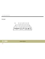
Page 22: ...Rear panel Operating elements e drum module 22...
Page 57: ...Notes MPS 500 USB 57...
Page 58: ...Notes e drum module 58...
Page 59: ......
Page 60: ...Musikhaus Thomann Hans Thomann Stra e 1 96138 Burgebrach Germany www thomann de...


