background image

Millennia Media HV-3R                                                                                                                  page 6 of 40 


Front Panel Functions 

 
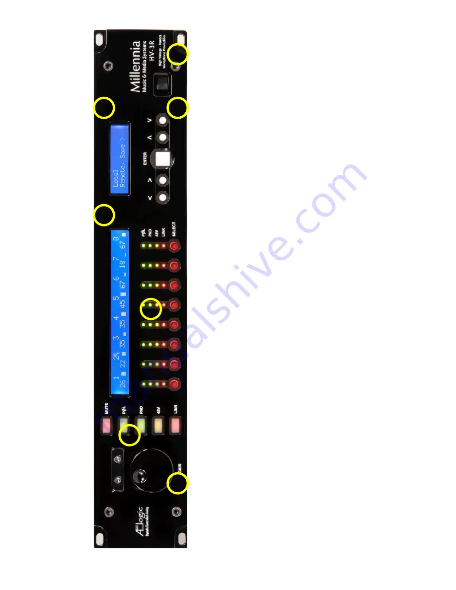
The 3/8” thick hand-machined aluminum front panel 
consists of two LCDs, one rotary encoder, 32 LED 
channel status indicators, and 18 functional 
pushbutton switches.  


1.


Large Rotary Encoder

 – Adjusts gain. 

2.


Column of Five Illuminated Pushbutton 

– Used to toggle a selected mic preamp’s 
parameters:  


MUTE

 Audio 


POL

arity inversion 


PAD

 14dB attenuation  


+48V

olt phantom power 


LINK

 Channels 


3.


Channel Status Indicators –  

Four LEDs 

per channel indicate status of channel’s 
parameters. Select button makes the 
selected channel’s controls editable. 


4.


Channel Display

 – Above the LED Matrix.  

It displays: 


Channel Number Indication 


Gain Setting 


Overload Indication 


Channel Mute 


Level Meter 
 

5. Menu Display – 

Indicates unit’s remote/local 

status and setup parameters. 

 
6. Menu Navigation

 – A group of five switches 

controlling menu navigation. The EDIT section 
provides extensive parametric setup of the 
HV-3R mic preamp. 
 

7. Power Switch – 

Turns the unit on and off. 

Summary of Contents for HV-3R

Page 1: ...Owner s Manual HV 3R Remote Controllable High Voltage Microphone Preamplifier Millennia Music Media Systems ...

Page 2: ...cene Window 21 Project and Scene Management 21 Creating a Project 21 Scene Window 21 Safety Prompts 21 Creating New Scenes 21 Renaming Scenes 21 Reordering Scenes 21 Recalling Scenes 22 Deleting Scene 22 Locking Scene Window Functions 22 Appending and Saving Scenes 22 Saving Scene Changes 22 REMOTE OPERATION WITH PRO TOOLS HD 23 Parameters for Remote Operation 23 Setting Up the HV 3R for Remote Op...

Page 3: ...ed as a stand alone locally controlled eight channel mic preamp similar to its sister product the renowned HV 3D Optional 130V mic inputs are available for use with high voltage microphones such as DPA 4003 and 4012 Two additional buffered balanced outputs per channel are available with the optional HROE expansion board via DB25 connectors Eight channels of internal A D conversation are also avail...

Page 4: ...s unit should be repaired or serviced by qualified personnel whenever The AC power cord has been damaged or Objects have fallen or liquid has spilled into any HV 3R unit or The unit does not function properly or exhibits a marked change in performance or The unit has been abused dropped or damaged or The unit has been exposed to rain or moisture Servicing Lethal voltages are found inside the HV 3R...

Page 5: ...ation Card Register online at http mil media com registration html or fill out the Owner s Registration Card and return to Millennia at your earliest ability The material contained in this manual consists of information that is property of Millennia and is intended solely for use by the purchasers of the equipment described in this manual Without express written permission Millennia prohibits the ...

Page 6: ...48Volt phantom power LINK Channels 3 Channel Status Indicators Four LEDs per channel indicate status of channel s parameters Select button makes the selected channel s controls editable 4 Channel Display Above the LED Matrix It displays Channel Number Indication Gain Setting Overload Indication Channel Mute Level Meter 5 Menu Display Indicates unit s remote local status and setup parameters 6 Menu...

Page 7: ...remote is enabled each Unit has a letter a through p after each channel number indicating the MIDI channel 1 through 16 see remote operation for more on setting the MIDI channel Gain Setting Gain is shown numerically under the channel number indication For example the number 35 would represent 35 dB of microphone voltage gain Overload Indication To the right of the channel number is an OL icon Cha...

Page 8: ...from the current Edit screen and when pressed repeatedly will eventually return to the top of the Main Menu Shown Below Getting Started The HV 3R is shipped to start up in Local mode Below is the default menu screen that appears when a Unit is powered up for the first time This menu screen is referred to as the top of the main menu For a description of the menu items and flow chart go to the secti...

Page 9: ...tion and many other settings can be saved in memory and recalled when needed 1 Choose Save from the main menu 2 Three choices will be presented Name Save and Del When saving a setup for the first time the Name choice may be desirable This option lets you name the Setup before choosing the memory location a Name Create a name for the setup by using the Up and Down arrows to change the character and...

Page 10: ...n That channel s output signal will now be opposite of the input signal Technically this is not a phase adjustment as the waveform does not shift in time Pad To attenuate a channel s output by 14 dB press the channel Select button then press the PAD button That channel s output signal will be padded by 14 dB though the gain shown in that channel s LCD will not change Phantom Power To apply 48 volt...

Page 11: ...me Save Del Name Enter Name Save Where Name Delete Setup Name Save Where Name Overwrite Setup No Yes Are You Sure No Yes Overwrite Setup No Yes IP Address Mode Unit ID MIDI Auto Save On Off Starting Setup Name IP Address Save DHCP IP Address Save 192 168 1 201 Mode Basic Advanced Startup Locked Locked Unlocked Startup Mode Local Remote See Advanced See Advanced ...

Page 12: ...Chooses Unit ID used to identify the unit over the LAN B MIDI Channel Assign OFF 1 16 Chooses MIDI channel used to communicate with the HV 3R C Startup Chooses startup options to be loaded when the HV 3R is powered on i Mode Chooses to startup in Local or Remote Mode a Local b Remote ii Setup Chooses memory location to be loaded a Location iii Auto Save Saves control settings 3 seconds after last ...

Page 13: ...le Setting Up Unit IDs and IP Address Setting Unit ID s and IP Addresses Each HV 3R needs to be set to its own unique Unit ID and IP address If units have the same ID or IP addresses there will be a conflict and the system will not work properly 1 Choose Setup from the main menu of the HV 3R 2 Choose MIDI make sure it is set to OFF and hit ENTER 3 Now Choose Unit ID set it to 01 or other number if...

Page 14: ... mode Remote mode can only be exited to Local mode by again pressing the and keys Saving the LAN settings and setting the startup mode Save HV 3R Settings 1 Choose Save from the main menu 2 To name the saved setup choose Name and use the arrow buttons to choose the desired title hit ENTER Otherwise choose Save and continue to step 3 3 Choose the desired memory location and hit ENTER 4 When prompte...

Page 15: ...appear if the install is successful Be sure the computer is set to IP address 192 168 1 200 Setting the Host Computer s IP Address XP 1 Go to Network right click on the Local Area Connection and open Properties 2 Double click on Internet Protocol TCP IP to open its properties 3 Select Use the following IP addresses 4 Enter 192 168 1 200 in IP Address 5 Enter 255 255 255 0 in Subnet mask 6 Click OK...

Page 16: ...rrors could also cause a red icon such as over temperature power supply out of range other networking errors etc Green Icon Functioning Normally Remote unit functioning normally Flashing Green Icon Functioning Normally Local Mode Remote unit is functioning normally but is in the local mode If the unit is in Local mode when Ælogic is started it won t appear Be sure to change the unit to Remote mode...

Page 17: ...screen shot on the previous page shows units 1 and 2 You can left click on any unit icon shown in the Unit Status window to immediately bring that unit s channel controls into the main screen Note the scroll bar at the bottom of the screen It allows the user to quickly scroll to any unit in the network You can also move the Control Section by using the Left and Right arrow keys on the keyboard Pre...

Page 18: ...rom the default the new Unit Name will now be displayed in the Unit Name box The Naming Window can also be accessed from the pull down menus Edit Unit Naming Channel Strip Display and Functions Channel Number Channel numbers appear at the top and bottom of the channel strip The preamp with Unit ID 1 will be assigned channels 1 8 Unit ID 2 will be assigned channels 9 16 Unit ID 48 will be assigned ...

Page 19: ...drop down box next to the LINK button or the Link Matrix When a link group is chosen the LINK button is automatically selected and illuminates red One link group can be assigned per channel If no link group is selected a depressed LINK switch will effectively do nothing Linked Gain Linked Gain faders move together maintaining the same distance they had when first linked together Once one fader rea...

Page 20: ...er linking and unlinking of channels and can be accessed via shortcut ctrl L or from the pull down menus Edit Link Name a Link Group by right clicking a Link Group number See the members of a group by double clicking the group s name Right click a link to bring up the channel naming dialog box ...

Page 21: ... a project itself must be created by doing a Save Use File Save to name the Project and find a location to save it File Save ctrl S will save any updates or changes to the project unless a new name is desired use File Save As shift ctrl S Scene Window Underneath the Scene Window there are four buttons Recall New Delete and Lock The functions of these buttons are explained below Safety Prompts In o...

Page 22: ...ing that it is active and cannot be deleted Locking Scene Window Functions Sometimes it may be necessary to disable the functions of the Scene Window The Lock button serves this purpose When the button is engaged the other three functions will turn dark grey and will no longer be functional Parameters in the Control Section faders Links function buttons etc will still be functional Appending and S...

Page 23: ...onnected and communicating with Pro Tools before use with the HV 3R 1 Connect the MIDI OUT port on the MIDI Interface to the MIDI IN port on the HV 3R 2 Connect the OUT of that unit to the IN of the next unit and so on 3 Connect the MIDI OUT port on the last HV 3R of the system to the MIDI IN port on the MIDI Interface Setting the MIDI Channel on the HV 3R 1 When you first turn on your HV 3R it sh...

Page 24: ...k OK to activate these settings If multiple HV 3R units are being used You can add up to nine HV 3R units to be controlled in Pro Tools In the Peripherals dialogue window choose PRE under the Type column as many times as desired for the number of HV 3Rs you have then assign the IN and OUT port numbers and MIDI channels that correspond to each HV 3R Remember that you can t have two HV 3Rs on the sa...

Page 25: ...on your Recording Interface that corresponds to the first output of the HV 3R 5 The first output will appear in the box you clicked while the next seven outputs will appear in the boxes to the right You can move the outputs of the HV 3R around Be sure that the chosen inputs in Pro Tools correspond to how they are connected physically to the Recording Interface It is crucial that all outputs and in...

Page 26: ...ds to The button labeled Gain Setting can control the HV 3R s gain but since the lowest gain setting on the HV 3R is 08 dB the first three settings 0dB 3dB and 6dB won t change the gain on the HV 3R The other buttons are reserved for use with the Digidesign PRE Pro Tools controls that do not work with the HV 3R Mute Gains 8dB Insert Mic Type HP filter Source Impedance Pad is 14dB not 18dB If you c...

Page 27: ...r preferences Ctrl N Create new project Ctrl O Open project Ctrl S Save Ctrl Z Undo 10 levels Double Click Group Title in Link Matrix Lists channels that are members of the group Double Click on unit icon in Unit Status box Gives voltage temperature and network data of unit Double Click Scene name Loads Scene F1 Help Menu Left Right keys on controls Move channels one over Right Click Group title n...

Page 28: ...tus Displays the status of various parameters currently active on the unit A LAN Address Displays the current IP Address the unit is using B Power Supply Displays the temperature and various voltages of the power supply i Temp C ii 48 iii 24 iv 5 v 3 3 C Firmware Ver Displays the current firmware version running on the unit D MAC Address Displays the MAC Address assigned to the unit See Basic 2 Ut...

Page 29: ...n be configured to either follow A or remain fixed at the values below by moving the associated jumpers Channels B 1 4 B 5 8 C 1 4 C 5 8 Polarity Follows A J1 Pins 1 2 J15 Pins 1 2 J3 Pins 1 2 J12 Pins 1 2 Polarity Fixed J1 Pins 2 3 J15 Pins 2 3 J3 Pins 2 3 J12 Pins 2 3 Pad Follows A J11 Pins 1 2 J13 Pins 1 2 J4 Pins 1 2 J6 Pins 1 2 Pad Fixed at 13 5 dB J11 Pins 2 3 J13 Pins 2 3 J4 Pins 2 3 J6 Pin...

Page 30: ... of this equipment in a residential area is likely to cause harmful interference in which case the user will be required to correct the interference at his or her own expense This product was testing for FCC compliance using a clamp on ferrite inductor If you are using Ethernet the inductor included with this unit must be attached to the Ethernet cable at the end connected to the HV 3R s RJ 45 5 c...

Page 31: ...nning with the internal clock make sure SW4 is in the INT position and no external clock is connected Sync Signals on the BNC connectors should conform to the AES 3id specification AES 3 through an XLR to BNC transformer Neutrik NADITBNC F or equivalent will work fine S PDIF works but is not specified Sample Rate kHz SW2 SW1 44 1 X1 44 48 X1 48 88 2 X2 44 96 X2 48 Clock Source SW4 Internal INT Ext...

Page 32: ...trol Change message and the X is a value from 0 to F in hex designating MIDI channel 1 16 The first byte is known as the Status Byte In Byte 2 the CC is a value from 00 to 7F in hex 0 to 127 in decimal This byte designates which Controller Number is being sent This byte is known as Data Byte 1 In Byte 3 the VV is a value from 00 to 7F in hex 0 to 127 in decimal This byte designates the Value being...

Page 33: ...ain Table Channel 2 Pad 0x12 18 Off 0x00 0 On 0x7F 127 48V 0x14 20 Polarity 0x15 21 Mute 0x17 23 Gain 0x19 25 See Gain Table Channel 3 Pad 0x22 34 Off 0x00 0 On 0x7F 127 48V 0x24 36 Polarity 0x25 37 Mute 0x27 39 Gain 0x29 41 See Gain Table Channel 4 Pad 0x32 50 Off 0x00 0 On 0x7F 127 48V 0x34 52 Polarity 0x35 53 Mute 0x37 55 Gain 0x39 57 See Gain Table Channel 5 Pad 0x42 66 Off 0x00 0 On 0x7F 127 ...

Page 34: ... 127 48V 0x54 84 Polarity 0x55 85 Mute 0x57 87 Gain 0x59 89 See Gain Table Channel 7 Pad 0x62 98 Off 0x00 0 On 0x7F 127 48V 0x64 100 Polarity 0x65 101 Mute 0x67 103 Gain 0x69 105 See Gain Table Channel 8 Pad 0x72 114 Off 0x00 0 On 0x7F 127 48V 0x74 116 Polarity 0x75 117 Mute 0x77 119 Gain 0x79 121 See Gain Table OMNI Reset HV 3R All Values to 0 0x0E 14 Irrelevant ...

Page 35: ...x00 8 1 0x01 8 2 0x02 8 3 0x03 9 4 0x04 12 5 0x05 15 6 0x06 18 7 0x07 21 8 0x08 14 9 0x09 17 10 0x0A 30 11 0x0B 33 12 0x0C 36 13 0x0D 39 14 0x0E 42 15 0x0F 45 16 0x10 48 17 0x11 51 18 0x12 54 19 0x13 57 20 0x14 60 21 0x15 63 22 0x16 66 23 0x17 69 Extra Gain Options 24 0x18 72 25 0x19 75 26 0x1A 78 27 0x1B 80 ...

Page 36: ... manual is offered by Millennia Media Visit http www puredata org for more information on PD The parameters available in the PD patch include all of the parameters currently available for control of the HV 3R via MIDI 1 Mute 2 Polarity Inversion 3 14dB Pad 4 Phantom Power 5 Gain 6 Reset The layout of the patch is meant to mimic the layout of the controls on the HV 3R s front panel There are eight ...

Page 37: ...it HV 3R powers up in Local Mode Create and save startup mode Unit doesn t appear in Ælogic Change mode to Remote on front panel Parameters saved in the startup register have changed You had been using the unit in LAN mode with auto save on It works in Pro Tools HD until the unit is powered down and back on Create and save startup mode for MIDI DHCP doesn t work You need to use a fixed IP address ...

Page 38: ...red Maximum Output Level 20 Hz 40 kHz 32 dBu Phantom Input Impedance 1 kHz 6 750 ohms Output Impedance 24 3 Ohms x2 DPA B K Mic Powering 130 V dc max non phantom Phantom Powering 48 V dc 2 V dc Power Consumption 125 watts maximum Power Requirements Selectable 100 120 200 240 V ac 50 60 Hz Dimensions Shipping Weight 19 W x 3 5 H x 16 D 19 lbs Millennia Media Inc reserves the right to change specifi...

Page 39: ...v 1 4 2 092309 Millennia Media HV 3R Maximum Non harmonic Spurious Tones Better than 140 dB Intrinsic Jitter 20Hz 20kHz 48kHz 50 pS RMS typical External Clock Lock Range 32 96 kHz all measurements with HV 3D in circuit ...

Page 40: ...factory at support mil media com to obtain a Return Authorization RA form Please include your shipping address daytime phone number and description of the problem Limits and Exclusions There are no express warranties except as listed above Millennia shall not be liable for special subsequent incidental consequential or punitive damages including but not limited to damage to recordings broadcasts m...

Reviews: