background image

OM-194 473 Page 20

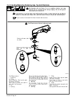
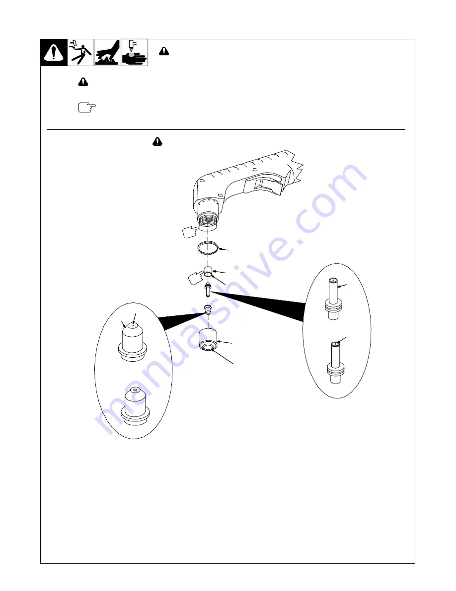
5-4. Checking/Replacing Retaining Cup, Tip, And Electrode

Overtightening will strip threads. Do not overtighten retaining cup during
assembly. Do not cross-thread parts causing stripping. Use care during torch
assembly and parts replacement.

Inspect shield cup, tip, and electrode for wear before cutting or whenever cutting speed has been significantly
reduced. Do not operate torch without a tip or electrode in place. Be sure to use genuine replacement parts.

A good practice is to replace both the tip and electrode at the same time.

802 465

Turn Off power source.

1

Shield Cup

2

O-Ring

Remove shield cup. Check cup for cracks,
and replace if necessary.

Check O-ring for cracks or worn spots, re-
place shield cup if necessary.

3

Tip

4

Opening

Remove tip. Check tip, and replace if open-
ing is deformed or 50% oversize. If inside of
tip is not clean and bright, clean with steel
wool. Be sure to remove any pieces of steel
wool afterwards.
5

Electrode

Check electrode. If center has a pit more
than a 1/16 in (2 mm) deep, remove and re-
place electrode.
6

Swirl Ring

7

O-Ring

Remove swirl ring. Check ring, and replace
if side holes are plugged.

Check O-ring for cracks or worn spots,
replace swirl ring if necessary.

8

O-Ring

Check O-ring for cracks or worn spots, and
replace if necessary.

Carefully reassemble parts in reverse order.

Make sure this area is clean of
any debris.

Make sure swirl ring is clean of any
debris and no holes are
obstructed.

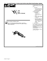
Turn Off power source before checking torch parts.

New

Worn

New

Worn

5

1/16 in

(2 mm)

Pit

4

3

6

1

2

7

8

Summary of Contents for Ice-12C Torch

Page 1: ...Spectrum Thunder And Ice 12C Torch Processes Description R Air Plasma Cutting and Gouging Air Plasma Cutter OM 194 473J April 2003 Visit our website at www MillerWelds com And Non CE Models ...

Page 2: ...lue established in 1929 This Owner s Manual is designed to help you get the most out of your Miller products Please take time to read the Safety precautions They will help you protect yourself against potential hazards on the worksite We ve made installation and operation quick and easy With Miller you can count on years of reliable service with proper maintenance And if for some reason the unit n...

Page 3: ...s 11 3 2 Specifications For CE Power Sources 11 3 3 Specifications For Torch 11 3 4 Duty Cycle And Overheating 11 3 5 Torch Dimensions And Weight 12 3 6 Selecting A Location 12 3 7 Connecting Work Clamp 13 3 8 Connecting Input Power 13 SECTION 4 OPERATION 14 4 1 Controls 14 4 2 Cutting Speed 14 4 3 Trigger Safety Lock 15 4 4 Sequence Of Operation 16 SECTION 5 MAINTENANCE TROUBLESHOOTING 17 5 1 Rou...

Page 4: ...e Directive 73 23 EEC Machinery Directives 89 392 EEC 91 368 EEC 93 C 133 04 93 68 EEC Standards Electromagnetic compatibility EMC Product standard for arc welding equipment EN50199 August 1995 Safety Requirements for Arc Welding Equipment part 1 EN 60974 1 1989 Arc Welding Equipment Part 1 Welding Power Sources IEC 974 1 September 1998 Draft revision Degrees of Protection provided by Enclosures I...

Page 5: ...an cause fatal shocks or severe burns The torch and work circuit are electrically live whenever the output is on The input power circuit and machine internal circuits are also live when power is on Plasma arc cutting requires higher voltages than welding to start and maintain the arc 200 to 400 volts dc are common but also uses torches designed with safety interlock systems which turn off the mach...

Page 6: ...lied respirator Fumes from cutting and oxygen deple tion can alter air quality causing injury or death Be sure the breathing air is safe D Do not cut in locations near degreasing cleaning or spraying oper ations The heat and rays of the arc can react with vapors to form highly toxic and irritating gases D Do not cut on coated metals such as galvanized lead or cadmium plated steel unless the coatin...

Page 7: ...o not overload building wiring be sure power supply system is properly sized rated and protected to handle this unit STATIC ESD can damage PC boards D Put on grounded wrist strap BEFORE handling boards or parts D Use proper static proof bags and boxes to store move or ship PC boards H F RADIATION can cause interference D High frequency H F can interfere with radio navigation safety services comput...

Page 8: ...Y 10018 Cutting And Welding Processes NFPA Standard 51B from National Fire Protection Association Batterymarch Park Quincy MA 02269 1 5 EMF Information Considerations About Welding Or Cutting And The Effects Of Low Frequency Electric And Magnetic Fields Welding or cutting current as it flows through the welding or cutting cables will cause electromagnetic fields There has been and still is some co...

Page 9: ...nants qui ont déjà reçu des combustibles D Portez des vêtements de protection exempts d huile tels que des gants en cuir une veste résistante des pantalons sans revers des bottes et un casque D Ne placez pas le poste sur une surface combustible ou au dessus de celle ci D Avant le coupage retirez tout combustible de vos poches par exemple un briquet au butane ou des allumettes Le fait de toucher à ...

Page 10: ... Material Safety Data Sheets MSDS et les instructions du fabricant pour obtenir plus de renseignements sur les métaux à couper les enrobages et les nettoyants D Travaillez dans un espace restreint uniquement s il est bien ventilé ou si vous portez un respirateur anti vapeurs Les vapeurs causées par le cou page et l épuisement de l oxygène peuvent altérer la qualité de l air et entraîner des blessu...

Page 11: ...rférences avec les équipements de ra dio navigation et de communication les services de sécurité et les ordinateurs D Demander seulement à des personnes qualifiées familiarisées avec des équipements électroniques de faire fonctionner l installation D L utilisateur est tenu de faire corriger rapidement par un électricien qualifié les interférences résultant de l installation D Si le FCC signale des...

Page 12: ...nt toujours en cours et les preuves continuent à être examinées En attendant que les conclusions finales de la recherche soient établies il vous serait sou haitable de réduire votre exposition aux champs électromagnétiques pendant le soudage ou le coupage Afin de réduire les champs électromagnétiques dans l environnement de travail respecter les consignes suivantes 1 Garder les câbles ensembles en...

Page 13: ...ll 3 1 Wear dry insulating gloves Do not wear wet or damaged gloves 3 2 Protect yourself from electric shock by insulating yourself from work and ground 3 3 Disconnect input plug or power before working on machine 4 Breathing cutting fumes can be hazardous to your health 4 1 Keep your head out of the fumes 4 2 Use forced ventilation or local exhaust to remove the fumes 4 3 Use ventilating fan to r...

Page 14: ...ssure Light V Volts Increase No Do Not Do This Temperature Protective Earth Ground Single Phase Constant Current Voltage Input On Off Percent Direct Current U0 Rated No Load Voltage Average U1 Primary Voltage U2 Conventional Load Voltage Line Connection I1max Rated Maximum Supply Current I2 Rated Welding Current X Duty Cycle Single Phase Static Frequency Converter Transformer Rectifier IP Degree O...

Page 15: ...e condition 3 3 Specifications For Torch Air cooled torch for plasma arc cutting PAC 35 duty cycle Compressor output 1 SCFM 28 3 L min at 40 PSI 276 kPa Safety interlock devices shut down power source Safety trigger guard Cutting capacity see Section 3 1 3 4 Duty Cycle And Overheating Duty Cycle is percentage of 10 min utes that unit can cut at rated load without overheating If unit overheats ther...

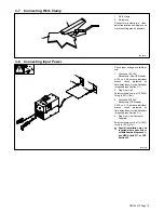
Page 16: ...o move unit 3 Non CE Or CE Plate Label Use label to determine input power needs 4 120 VAC Receptacle Non CE Models 5 230 VAC Receptacle CE Models Locate unit near correct input power supply Y Special installation may be required where gasoline or volatile liquids are present see NEC Article 511 or CEC Section 20 6 3 4 in 171 mm 17 in 432 mm Movement 1 2 Location And Airflow 3 Dimensions And Weight...

Page 17: ... circuit protected by time delay fuses or circuit breaker is required see Section 3 1 2 Plug From Unit Select extension cord of 12 AWG for up to 53 ft 16 m 3 Grounded 230 VAC Receptacle CE Models A 230 volt 10 ampere individual branch circuit protected by time delay fuses or circuit breaker is required see Section 3 1 4 Plug From Unit Customer Supplied Select extension cord of 14 AWG for up to 133...

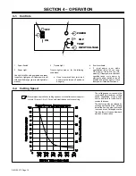
Page 18: ...on CE models 186 to 274 vac CE models If input power is outside of specified range cycle power by placing the power switch in the off position and back on again Check input power if problem continues 4 2 Cutting Speed The cutting speed curve shows the recommended maximum cutting speed capabilities of the power source and torch for mild steel of various thickness The best cut quality is achieved by...

Page 19: ...OM 194 473 Page 15 4 3 Trigger Safety Lock Trigger Locked Trigger Unlocked 1 Trigger 801 545 A 1 ...

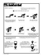
Page 20: ... normal to sometimes see moisture come out the end of the torch As a convenience the torch can be set up with two cutting combinations either drag or non shielded cutting The torch comes standard with drag cutting Maximum performance on thicker materials can be obtained by using non shieldedcutting with a 1 16 1 8 in 1 6 3 2 mm standoff 197 567 196 929 Use retaining cup 197 567 and drag shield 196...

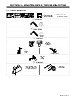
Page 21: ...en during severe conditions Each Use Check Torch Tip Electrode And Shield Cup Every Week Check Shield Cup Shutdown System 3 Months Replace Damaged Or Unreadable Labels Replace Cracked Parts Torch Body Cable Tape Torn Outer Covering 6 Months Blow Out Or Vacuum Inside Check Compressor Filter Clean With A Damp Cloth Or Replace If Necessary ...

Page 22: ...Lights if input power is not within specification 93 to 137 vac Power must be reset whenever the input voltage shutdown is activated 2 Torch Shield Cup Turn Power On and loosen shield cup If shutdown system works properly trouble light comes on If not turn power Off and check for loose shield cup Check consumables see Sections 5 4 and Parts List If system works properly retighten cup and reset pow...

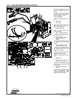
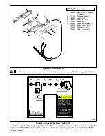
Page 23: ...tion Terminal RC11 ELECT WHITE Connect female friction terminal on end of white leads to RC11 ELECT WHITE 6 Female And Male Friction Terminal RC7 PILOT RED Connect female friction terminal on end red leads to RC7 PILOT RED Tighten strain relief nut Tighten strain relief around cable Work Cable Connections Remove existing work cable from unit 7 Strain Relief Be sure to allow some work cable slack i...

Page 24: ... ring for cracks or worn spots re place shield cup if necessary 3 Tip 4 Opening Remove tip Check tip and replace if open ing is deformed or 50 oversize If inside of tip is not clean and bright clean with steel wool Be sure to remove any pieces of steel wool afterwards 5 Electrode Check electrode If center has a pit more than a 1 16 in 2 mm deep remove and re place electrode 6 Swirl Ring 7 O Ring R...

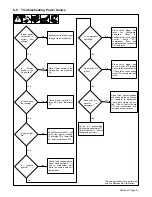
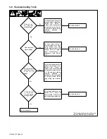
Page 25: ...own unit temperature No Yes Press torch trigger and listen for compressor operation Check for Postflow air at torch Check Control board PC1 compressor filter and compressor connections to PC1 and torch Yes No Is compressor operating Press torch trigger and check if pilot arc ignites Check torch consumables Check torch connections relay CR1 compressor and torch Yes No Does pilot arc ignite Place to...

Page 26: ...bles as necessary see Section 5 4 Do sparks come out of top of cut or cut is not clean No Yes Torch travel speed too fast reduce travel speed see Section 4 2 Clean or replace torch consumables as necessary see Section 5 4 Be sure work clamp is securely attached to workpiece Unit not capable of cutting metals thicker than rating see Section 3 1 Is Trouble light On unit has no cutting output Yes Che...

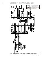
Page 27: ...OM 194 473 Page 23 SECTION 6 ELECTRICAL DIAGRAM Figure 5 1 Circuit Diagram For 120 Volts AC Power Source Non CE Models 202 707 ...

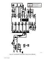
Page 28: ...OM 194 473 Page 24 202 701 Figure 5 2 Circuit Diagram For 230 Volts AC Power Source CE Models ...

Page 29: ...OM 194 473 Page 25 Notes ...

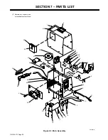
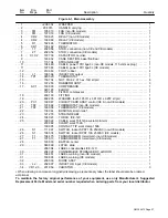
Page 30: ... Page 26 SECTION 7 PARTS LIST Figure 6 1 Main Assembly Hardware is common and not available unless listed 802 462 D 2 4 5 6 7 8 9 10 11 12 13 14 15 16 19 20 21 22 23 25 24 26 27 28 29 30 31 17 18 32 33 5 1 3 4 34 ...

Page 31: ...RCUIT CARD ASSY control CE non CE models 1 21 TP2 197 892 THERMOSTAT non CE models 1 21 TP2 199 058 THERMOSTAT CE models 1 22 138 044 BUSHING strain relief 1 23 121 276 STRAIN RELIEF 1 24 196 923 TORCH ICE 12C 1 25 199 022 CABLE work 15ft 12ga w clamp term 1 203 988 CLAMP work 150A 1 199 995 CONTACT TIP work clamp 150A 2 26 S1 111 997 SWITCH rocker SPST 10A 250VAC non CE models 1 26 S1 196 574 SWI...

Page 32: ...eld 196 929 S 206 304 206304 Retaining Cup 197567 Tip 196926 Electrode 196925 Swirl Ring 196927 O Ring 196935 Retaining Cup 196928 Drag Shield 196929 1 8 3mm stand off recommended Apply silicone grease 169 231 before installing Turn off power before checking torch parts Check before each use and hourly during operation CAUTION FAILURETO RE PLACEWORNTIP ORELECTRODE WILLRUINTORCH ANDVOID WARRANTY IC...

Page 33: ...Notes ...

Page 34: ...Notes ...

Page 35: ...rols Accessory Kits Replacement Parts No labor Spoolmate Spoolguns Canvas Covers Miller s True Blue Limited Warranty shall not apply to 1 Consumable components such as contact tips cutting nozzles contactors brushes slip rings relays or parts that fail due to normal wear Exception brushes slip rings and relays are covered on Bobcat Trailblazer and Legend models 2 Items furnished by Miller but manu...

Page 36: ... complete and retain with your personal records Always provide Model Name and Serial Style Number Call 1 800 4 A Miller or see our website at www MillerWelds com to locate a DISTRIBUTOR or SERVICE AGENCY near you Welding Supplies and Consumables Options and Accessories Personal Safety Equipment Service and Repair Replacement Parts Training Schools Videos Books Technical Manuals Servicing Informati...

Reviews: