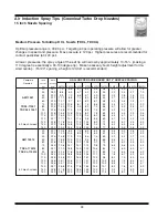
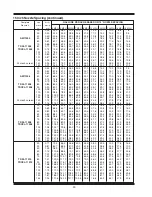
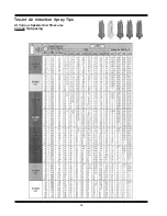
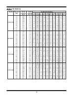
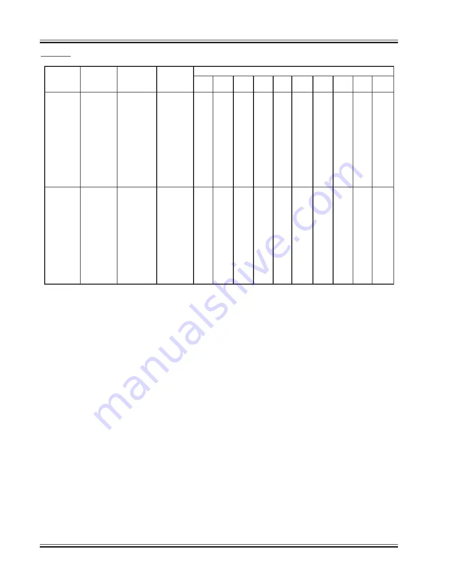
40
Tip Size
Pressure
Nozzle
Nozzle
20 INCH TIP SPACING
(PSI)
Capacity
Capacity
5
6
7
8
10
12
13
14
16
18
(GPM)
(oz/min)
MPH MPH MPH MPH MPH MPH MPH MPH MPH MPH
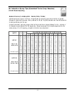
15
0.61
78
36
30
26
23
18.1
15
13.9
12.9
11.3
10.1
20
0.71
91
42
35
30
26
21.1
18
16
15.1
13.2
11.7
25
0.79
101
47
39
34
29
23
20
18
17
14.7
13.0
30
0.87
111
52
43
37
32
26
22
20
18
16
14.4
35
0.94
120
56
47
40
35
28
23
21
20
17
16
XR11010-SS
40
1.00
128
59
50
42
37
30
25
23
21
19
17
50
1.12
143
67
55
48
42
33
28
26
24
21
18
60
1.22
156
72
60
52
45
36
30
28
26
23
20
70
1.32
169
78
65
56
49
39
33
30
28
25
22
80
1.41
180
84
70
60
52
42
35
32
30
26
23
90
1.50
192
89
74
64
56
45
37
34
32
28
25
100
1.58
202
94
78
67
59
47
39
36
34
29
26
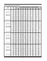
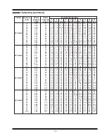
15
0.92
118
55
46
39
34
27.3
23
21
19.5
17.1
15.2
20
1.06
136
63
52
45
39
31.5
26
24
22
19.7
17.5
25
1.19
152
71
59
50
44
35
29
27
25
22
19.6
30
1.30
166
77
64
55
48
39
32
30
28
24
21
35
1.40
179
83
69
59
52
42
35
32
30
26
23
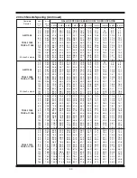
XR11015-SS
40
1.50
192
89
74
64
56
45
37
34
32
28
25
50
1.68
215
100
83
71
62
50
42
38
36
31
28
60
1.84
236
109
91
78
68
55
46
42
39
34
30
70
1.98
253
118
98
84
74
59
49
45
42
37
33
80
2.12
271
126
105
90
79
63
52
48
45
39
35
90
2.25
288
134
111
95
84
67
56
51
48
42
37
100
2.37
303
141
117
101
88
70
59
54
50
44
39
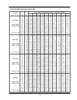
20 Inch Tip Spacing (continued)
Summary of Contents for 500 BW
Page 6: ......
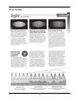
Page 31: ...27 Spray Tip Wear...
Page 38: ...34 TeeJet Air Induction Spray Tips At Various Speeds And Pressures 20 Inch Tip Spacing...
Page 94: ......
Page 96: ...2007 by Miller St Nazianz Inc...


