background image

70

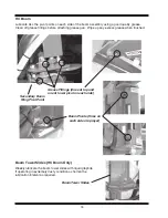
Hydraulic Boom Operation

Three types of hydraulically operated booms are available.  They are EF Booms, EFT Booms and
HC Booms.

DANGER

To avoid personal injury or death, KEEP clear of ALL electrical power lines
when operating sprayer or when folding or unfolding booms.

WARNING

To avoid personal injury, make sure that everyone is at a safe distance from the
sprayer before folding or unfolding the sprayer boom.  Keep a safe distance
from the boom while in operation.  Hydraulic booms may move suddenly
without warning.

EF & EFT Boom

After the sprayer and hydraulic hoses have been properly attached to the tractor, unfold the boom
using the following procedure:

1.

Raise the complete boom until the boom wings clear the transport rest.

2.

Place the tractor in park and/or set the brakes and stop the engine.

3.

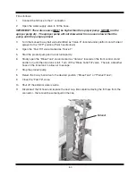
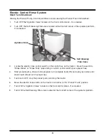
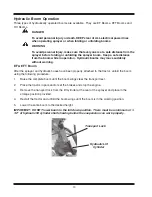
Remove the transport lock from the lift cylinder at the rear of the sprayer and place in the
storage position provided.

4.

Restart the tractor and unfold the boom wings until the boom is in the working position.

5.

Lower the entire boom to the desired height.

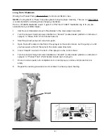
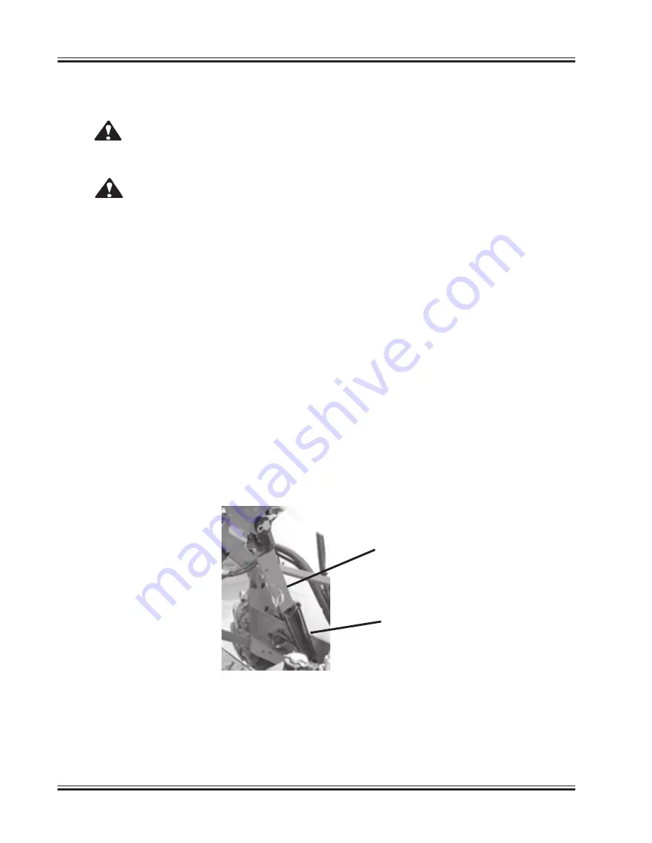
IMPORTANT: DO NOT lower boom to the full down position.  There must be a minimum of 1-
1/2” of hydraulic lift cylinder shaft showing before the suspension can work properly.

Hydraulic Lift

Cylinder

Transport Lock

Summary of Contents for 500 BW

Page 1: ...P O BOX127 ST NAZIANZ WI 54232 920 773 2121 FAX 920 773 1200 TRAILER SPRAYER OPERATOR S MANUAL DO NOT OPERATE THIS EQUIPMENT UNTIL THIS MANUAL HAS BEEN READ AND UNDERSTOOD Part Number 07 09145D Novem...

Page 2: ...ld void the warranty MACHINE SERIAL NUMBER The machine serial number is located on the left side of the pump mount shield For your convenience refer to this number and your product model number when r...

Page 3: ...Tips Greenleaf Turbo Drop Nozzles 28 Air Induction Spray Tips Greenleaf Turbo Drop Nozzles 31 TeeJet Air Induction Spray Tips 34 TeeJet Application Rates in Gallons Per Acre 35 TeeJet FloodJet Wide A...

Page 4: ...er at the time the unit is delivered Check off each item as you explain it to the customer Sprayers with power take off PTO driven pumps must have the tractor drawbar adjusted per instruc tions on pag...

Page 5: ...er at the time the unit is delivered Check off each item as you explain it to the customer Sprayers with power take off PTO driven pumps must have the tractor drawbar adjusted per instruc tions on pag...

Page 6: ......

Page 7: ...on MAKE SURE that every individual who operates or works with this equip ment whether family member or employee is familiar with these safety precautions Miller St Nazianz provides guards for exposed...

Page 8: ...actor engine Failure to follow this procedure may result in serious bodily injury AVOID high pressure fluids Escaping fluid under pressure can penetrate skin causing serious injury DO NOT exceed a max...

Page 9: ...n folding or unfolding boom KEEP clear of ALL electrical power lines when operating sprayer or when folding or unfolding booms Chemical Safety Handle ALL agricultural chemicals with care Use chemicals...

Page 10: ...ur dealer for replacements Shield Missing decal Part No 331639B2 This decal is mounted on the driveline and is visible only if the plastic shield is removed Danger Rotating Driveline decal Part No 329...

Page 11: ...7 Decal Before Operating Part No 16 20178 Agricultural Chemicals Part No 07 05527 Safety Decals continued Decal Hydraulic Fluid Pressure Part No 21 09024...

Page 12: ...ARNING Avoid bodily injuries from hydraulic oil and gas under pressure Before removing or charging accumulator 1 Start engine 2 Relieve the pressure in the circuit by collapsing the cylinder and holdi...

Page 13: ...9 Safety Decals continued Decal Hydraulic Fluid Pressure Part No 21 09024 Decal Pinch Point Qty 2 Part No 21 09025...

Page 14: ...SMV Emblem Part No 907224 Yellow Reflector Qty 2 Left Side Shown Part No 907220 Red Reflector Qty 2 Left Side Shown Part No 907219 Yellow Reflector Qty 2 Part No 907220 Yellow Reflector Qty 2 Part No...

Page 15: ...heels from sprayer centerline 3 Place a hydraulic or screw jack under the sprayer frame behind the axle on the same side as the wheel to be adjusted Jack up the sprayer high enough to raise the wheel...

Page 16: ...a tractor having a 540 RPM PTO unless your sprayer has a 1000 RPM centrifugal pump Optional Adjust the tractor drawbar so the distance from the end of the PTO shaft to the center of the draw bar hitc...

Page 17: ...tched to the tractor Adjust the hitch as follows a Remove the four bolts securing the hitch to the flanges on the sprayer tongue b Raise or lower the hitch or rotate the hitch 180 to a position that w...

Page 18: ...osition Jack In Stored Position Pin and Clip Pin and Clip c Position the jack onto the storage mount on the sprayer frame d Secure in place with the pin and clip Important Always secure the jack in th...

Page 19: ...toward the sprayer and slide the driveline onto the tractor s PTO output shaft as far as possible 9 Release the collar Pull the driveline to the rear toward the sprayer until the collar snaps into th...

Page 20: ...isconnect and reverse the sprayer hose connections at the tractor The pump should oper ate IMPORTANT Always use the float position to STOP the hydraulic sprayer pump Note If sprayer is being hitched t...

Page 21: ...ut OFF d Using the pressure tube coupler and fittings connect the tube in the control wiring harness to the tube in the extension wiring harness Install the coupler outside the tractor cab in case it...

Page 22: ...ayer are maked with colored tie wraps to identify the hoses for proper connection to the tractor The pair of hoses for the fold IN or OUT will have one color and the boom UP or DOWN will be another co...

Page 23: ...losed Center Hydraulics turn the flow rate on your tractor hydraulic system down to 5 to 6 GPM and try the sprayer boom functions If the sprayer functions are not satisfac tory the valve block located...

Page 24: ...ctor WARNING Hydraulic oil under pressure can spray into eyes and cause physical injury Follow tractor operator manual instructions for shutting off hydraulic supply and relieving hydraulic pressure o...

Page 25: ...stem Uncouple the hoses from the tractor remotes 7 Disconnect electrical connections on all sprayer accessories 8 Pull collar on tractor end of implement driveline to the rear Slide the driveline off...

Page 26: ...r moving objects IMPORTANT NEVER exceed the maximum towing speed of 20 MPH 32 KMH Reduce speed when turning or traveling on rough or hilly terrain Transport Lighting The sprayer is equipped with trans...

Page 27: ...Connect the WHITE wire to the Positive 12 volt power source on your tractor Connect the BLACK wire to the Negative ground source on your tractor or a good ground Fence Line Kit Right Side Left Side or...

Page 28: ...mation This section includes general information operators will find helpful for cost effective sprayer opera tion Measuring Travel Speed Measure a test course in the area to be sprayed or in an area...

Page 29: ...d on spraying water which weighs 8 34 lbs per US gallon conver sion factors must be used when spraying solutions which are heavier or lighter than water To determine the proper size nozzle for the sol...

Page 30: ...a cent tips which is critical to uniform distribution Unless otherwise specified at the time of manufacture your sprayer is equipped with flat fan spray nozzles having the following characteristics Vo...

Page 31: ...27 Spray Tip Wear...

Page 32: ...14 0 11 2 9 3 8 0 7 0 5 6 4 7 4 0 3 5 3 1 TDCXL 11001 90 0 15 14 8 11 9 9 9 8 5 7 4 5 9 4 9 4 2 3 7 3 3 100 0 16 15 6 12 5 10 4 8 9 7 8 6 3 5 2 4 5 3 9 3 5 110 0 17 16 4 13 1 10 9 9 4 8 2 6 6 5 5 4 7...

Page 33: ...29 7 25 5 22 3 17 8 14 9 12 7 11 1 9 9 50 mesh screen 140 0 47 46 3 37 0 30 8 26 4 23 1 18 5 15 4 13 2 11 6 10 3 150 0 48 47 9 38 3 31 9 27 4 23 9 19 2 16 0 13 7 12 0 10 6 20 0 21 21 0 16 8 14 0 12 0...

Page 34: ...7 22 9 130 1 08 107 1 85 7 71 4 61 2 53 6 42 8 35 7 30 6 26 8 23 8 24 mesh screen 140 1 12 111 2 88 9 74 1 63 5 55 6 44 5 37 1 31 8 27 8 24 7 150 1 16 115 1 92 1 76 7 65 8 57 5 46 0 38 4 32 9 28 8 25...

Page 35: ...L 11001 80 0 14 10 5 8 4 7 0 6 0 5 2 4 2 3 5 3 0 2 6 2 3 TDCXL 11001 90 0 15 11 1 8 9 7 4 6 4 5 6 4 5 3 7 3 2 2 8 2 5 100 0 16 11 7 9 4 7 8 6 7 5 9 4 7 3 9 3 4 2 9 2 6 110 0 17 12 3 9 8 8 2 7 0 6 2 4...

Page 36: ...22 3 19 1 16 7 13 4 11 1 9 6 8 4 7 4 50 mesh screen 140 0 47 34 7 27 8 23 1 19 8 17 4 13 9 11 6 9 9 8 7 7 7 150 0 48 35 9 28 7 23 9 20 5 18 0 14 4 12 0 10 3 9 0 8 0 20 0 21 15 7 12 6 10 5 9 0 7 9 6 3...

Page 37: ...22 1 19 3 17 2 130 1 08 80 3 64 3 53 6 45 9 40 2 32 1 26 8 23 0 20 1 17 9 24 mesh screen 140 1 12 83 4 66 7 55 6 47 6 41 7 33 3 27 8 23 8 20 8 18 5 150 1 16 86 3 69 0 57 5 49 3 43 1 34 5 28 8 24 7 21...

Page 38: ...34 TeeJet Air Induction Spray Tips At Various Speeds And Pressures 20 Inch Tip Spacing...

Page 39: ...9 5 2 4 6 90 0 23 29 18 15 2 13 0 11 4 9 1 7 6 7 0 6 5 5 7 5 1 100 0 24 31 19 15 8 13 6 11 9 9 5 7 9 7 3 6 8 5 9 5 3 15 0 12 15 9 5 7 9 6 8 5 9 4 8 4 0 3 7 3 4 3 0 2 6 20 0 14 18 11 1 9 2 7 9 6 9 5 5...

Page 40: ...70 0 66 84 52 44 37 33 26 22 20 1 18 7 16 3 14 5 80 0 71 91 56 47 40 35 28 23 21 6 20 1 17 6 15 6 90 0 75 96 59 50 42 37 30 25 22 8 21 2 18 6 16 5 100 0 79 101 63 52 45 39 31 26 24 22 3 19 6 17 4 15 0...

Page 41: ...75 65 52 44 40 37 33 29 80 1 41 180 112 93 80 70 56 47 43 40 35 31 90 1 50 192 119 99 85 74 59 50 46 42 37 33 100 1 58 202 125 104 89 78 63 52 48 45 39 35 15 0 92 118 73 61 52 46 36 4 30 28 26 0 22 8...

Page 42: ...4 2 3 7 3 3 80 0 21 27 12 10 4 8 9 7 8 6 2 5 2 4 8 4 5 3 9 3 5 90 0 23 29 14 11 4 9 8 8 5 6 8 5 7 5 3 4 9 4 3 3 8 100 0 24 31 14 11 9 10 2 8 9 7 1 5 9 5 5 5 1 4 5 4 0 15 0 12 15 7 1 5 9 5 1 4 5 3 6 3...

Page 43: ...39 33 28 25 20 16 15 1 14 0 12 3 10 9 80 0 71 91 42 35 30 26 21 18 16 2 15 1 13 2 11 7 90 0 75 96 45 37 32 28 22 19 17 1 15 9 13 9 12 4 100 0 79 101 47 39 34 29 23 20 18 16 8 14 7 13 0 15 0 37 47 22...

Page 44: ...69 78 65 56 49 39 33 30 28 25 22 80 1 41 180 84 70 60 52 42 35 32 30 26 23 90 1 50 192 89 74 64 56 45 37 34 32 28 25 100 1 58 202 94 78 67 59 47 39 36 34 29 26 15 0 92 118 55 46 39 34 27 3 23 21 19 5...

Page 45: ...41 TeeJet FloodJet Wide Angle Flat Spray Tips At Various Speeds And Pressures 40 Inch Tip Spacing...

Page 46: ...prayer Triple Electric Control Standard This system consists of three electric ball valves and a electric pressure regulating valve which are all mounted on the top of the boom mid section of the spra...

Page 47: ...PRESSURE ADJUST toggle switch which allows the operator to INCREASE or DE CREASE the pressure of the liquid supplied to the boom sections When the operator re leases the switch after adjusting the pr...

Page 48: ...t Center Right Center and Right The control box has additional switches to provide four section boom control Valve Control Center The valve control center is located in front of the sprayer platform T...

Page 49: ...he agitation throttling valve will be the first valve located at the bottom of the valve control center tower See preceeding page for location There are four agitation jets inside the product tank Two...

Page 50: ...e system The throttling valve should remain completely open for the self cleaning filter to operate properly When the cannister is removed from the filter head the throttling valve MUST be closed To c...

Page 51: ...dard Configuration 1 Remove the lid from the top of the product tank Fill the tank using a garden hose or similiar means 2 Replace the lid when complete Filling With Transfer Pump Your sprayer is equi...

Page 52: ...identified as Valve F located on the left side of the sprayer directly behind the step Fill as follows 1 Connect the fill hose to the 2 connector 2 Open the water supply valve to fill the hose IMPORT...

Page 53: ...cated under the platform on left side of sprayer to the Product Tank position handle pointed toward rear of sprayer If Equipped With Electric Control Rinse System Located under the operator platform o...

Page 54: ...nd pump Make sure the three way valve if so equipped is open to the product tank 4 Fold out the boom Refer to the Hydraulic Booms section of this manual for instructions 5 Start the tractor Start the...

Page 55: ...sole master switch ON 3 Press the Self Test button so the red light stays on 4 Press Enter so the red light stays on 5 Press the No 5 key and the No 0 key 6 Press Enter again Now the RAVEN rate contro...

Page 56: ...ual for instruc tions 8 Start the sprayer and run at desired RPMs and pressure 9 While parked collect the liquid from the nozzle Hold a container Miller Calibration Jar Part No 07 11360 graduated in o...

Page 57: ...ck all the tie down straps for proper tightness 1 Fill all tanks completely 2 Check the straps for proper tighness Straps should be snug around the tank 3 If straps require tightening adjust each stra...

Page 58: ...54 Instructions Valve Settings For Accessory Kits Refer To The Operator s Manual For Detailed Instructions...

Page 59: ...d under the product tank is OPEN 3 Start the product pump and run at rated speed 4 OPEN the Chemical Fill Control valve 5 If you are going to use the measuring marks on the chemical inductor tank to m...

Page 60: ...n is supplied with water from the optional 12 volt electric pump the water will come from the rinse tank 7 Always turn the valve under the chemical inductor tank OFF before turning the Chemical Fill v...

Page 61: ...case 10 If you are mixing more than one chemical into the product tank you should check with your chemical supplier to make sure you add the chemicals in the correct sequence to insure proper mixing...

Page 62: ...he control center is located at the front of the sprayer The water supplied will be contaminated with diluted mixed chemical To Operate 1 Start the product pump Be certain to have water in the product...

Page 63: ...trol center 3 Remove the hand gun from the storage bracket and rinse the chemical inductor tank 4 When finished turn OFF the electric switch point the hand gun into the chemical inductor tank and sque...

Page 64: ...s available for the product tank of your sprayer This sight gauge is a clear tube mounted to the product tank on the front side This gauge is visible from the operators position and is used as an indi...

Page 65: ...he sprayer on the control stand 3 rinse balls located in the product tank The rinse system can do two different functions Rinse the product pump controls and boom lines and leave the product tank undi...

Page 66: ...tform on left side of sprayer to Rinse Tank Point handle forward 4 Slowly open the Fast Fill valve marked as Valve F and let run until rinse tank is full Turn off Fast Fill valve There is a breather h...

Page 67: ...pen the Fast Fill valve marked as Valve F 5 Start the product pump and run at full capacity 6 Slowly open the Rinse Tank valve marked as Valve A located on the front control stand and let run until th...

Page 68: ...to Rinse Water or Rinse Tank depending on which control switch your sprayer has 4 Slowly open the Fast Fill valve marked as Valve F and let run until rinse tank is full Turn off Fast Fill valve There...

Page 69: ...ward rear of sprayer 4 Open the Fast Fill valve marked as Valve F 5 Start the product pump and run at full capacity 6 Slowly open the Rinse Tank valve marked as Valve A located on the front control st...

Page 70: ...perator platform If so desired Self Cleaning Filter Valve Agitation Valve 3 Turn the manual 3 way ball valve identified as Valve E located under platform on left side of sprayer to Rinse Tank Point ha...

Page 71: ...rm on left side of sprayer to Rinse Tank Point handle forward 3 Start the product pump and run at full speed 4 Open Valve B located in the front of the sprayer on the control stand Let the pump run un...

Page 72: ...e control switch on the control box on the tractor Move the switch to Rinse Water or Rinse Tank depending on which control switch your sprayer has 4 Start product pump drive at normal speed turn compl...

Page 73: ...ank position HC control and or Product Tank Rinse switch to the OFF position and the Product Tank Rinse Tank switch to the Product Tank position Standard electric control 6 Drive at normal speed turn...

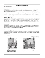
Page 74: ...r the sprayer and hydraulic hoses have been properly attached to the tractor unfold the boom using the following procedure 1 Raise the complete boom until the boom wings clear the transport rest 2 Pla...

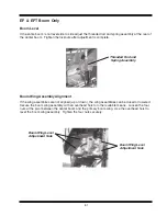
Page 75: ...he boom stabilizer arm and put in place on the hydraulic lift cylinder 5 Restart the tractor and lower the boom on to the boom transport rest EFT Boom After the sprayer booms have been unfolded and lo...

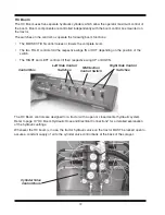
Page 76: ...sition of the switch The RIGHT and LEFT controls tilt their respective wing UP or DOWN Control Box Left Side Control Switches Mid Section Control Switch The HC Boom controls are designed for a tractor...

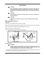
Page 77: ...ly Grease with a high quality grease before starting work each day or after every 8 hours of operation Clean and grease PTO shaft before each prolonged period of nonuse Grease the shield tubes to prev...

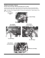
Page 78: ...e Clean off grease fittings before attaching grease gun Wipe up any excess grease when finished NOTE There are a total of 9 grease fittings on the EF boom assembly and 11 grease fittings on the EFT bo...

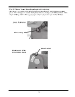
Page 79: ...ter Boom Mounting Arm Pivot Points Lubricate ALL the pivot points on each mounting arm and the center pivot using a good quality grease The center pivot is located directly behind the slow moving vehi...

Page 80: ...al as required HC Boom Lubricate ALL the pivot points on each side of the boom assembly using a good quality grease Clean off grease fittings before attaching grease gun Wipe up any excess grease when...

Page 81: ...aily The recommended tire pressure is 12 4 24 6 ply tires 24 psi 11 2 38 4 ply tires 18 psi Filters Remove and clean the water filters daily Clean the filters on the optional foam marking system at in...

Page 82: ...king with chemicals Keep protective clothing clean and in good condition or discard IMPORTANT It is very important that you thoroughly clean the sprayer inside and out Cleaning the Inside of the spray...

Page 83: ...ll inductor valves to insure antifreeze has been run through the entire inductor system Foam Marker IMPORTANT The liquid lines and tank must be drained completely prior to storage If liquid in this sy...

Page 84: ...tening the nuts on the extension spring for the breakaway increases the tension Turning the nuts out decreases the tension The springs are located between the primary and secondary boom wings Boom Lev...

Page 85: ...Boom Wing Level Adjustment Nuts Boom Wing Assembly Alignment If the wing assemblies are not aligned up or down the wing assemblies can be raised or lowered Secure the boom wing assembly with an overhe...

Page 86: ...tight Recheck the boom breakaway tension and adjust if necessary Boom Breakaways The tension of the boom breakaways should be checked and adjusted as needed If the tension on the breakaways is too gr...

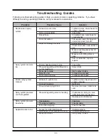
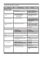
Page 87: ...bris if any Make sure emergency shut off valve is open Make sure throttling valve is open Pump is defective repair or replace Clean filter Adjust valve Verify spray tip size Increase travel speed Incr...

Page 88: ...mpletely open Self cleaning filter ON OFF valve not open Pluggedagitationnozzle s To much oil flow from tractor Check and replace fuse Clean and check connection Check for break in wire Verify calibra...

Page 89: ...out of adjustment Bad cylinder seals Dirt in HC valve block spool See dealer for service Slowdown Replaceshockabsorber Replace seals Replace seals in valve Adjust coil spring Adjust top boom wing sup...

Page 90: ...17 13 25 18 5 16 24 12 9 19 14 25 20 3 8 16 20 15 30 23 45 35 3 8 24 23 17 35 25 50 35 7 16 14 32 24 50 35 70 55 7 16 20 36 27 55 40 80 60 1 2 13 50 35 75 55 110 80 1 2 20 55 40 90 65 120 90 9 16 12...

Page 91: ...cknut off until washer bottoms out at top of groove 3 Hand tighten fitting until backup washer or washer face if straight fitting bottoms on face and O ring is seated 4 Position angle fittings by unsc...

Page 92: ...n good condition or discard To clean screens 1 Use caution when removing filter canisters or boom lines There could be residual pressure in the filter or boom lines 2 Place a container under the filte...

Page 93: ...ozzle valve When handle is at a right angle from the valve it is in the OFF position 3 Start the sprayer and spray as normal 4 When finished turn OFF the boom stop the tractor and walk to the end of t...

Page 94: ......

Page 95: ...inety 90 days of the installation date Misuse The provisions of this warranty shall not apply to any Miller Sprayer which has been subject to misuse negligence alteration or accident or which shall ha...

Page 96: ...2007 by Miller St Nazianz Inc...

Reviews: