46
Standard Primary Filter
Your sprayer is equipped with a primary filtration system. This filter could be in the form of a “Y”
strainer (standard) or a self cleaning filter (optional). The filter is located on the right side of the
sprayer under the sprayer platform. The filter is installed on the pressure side of the pump and has
a 50 mesh screen. Other size mesh screens are available through your local Miller dealer parts
department.
Self Cleaning Filter (Optional)
Refer to the “Maintenance” section of this manual for filter maintenance interval and
procedures
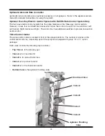
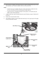
A self cleaning filter is an optional accessory. This filter has a throttling valve located in the front left
hand side of the sprayer. A quick coupler system and hose is mounted to the bottom of the filter
cannister. The unmixed chemical that does not go through the 50 mesh screen is returned to the
product tank through the rear agitation jets, reagitated and sent back through the system.
•
The throttling valve should remain completely open for the self cleaning filter to operate properly.
•
When the cannister is removed from the filter head, the throttling valve MUST be closed.
To clean the filter screen:
DANGER
Agricultural chemicals are TOXIC, chemicals not safely used, handled, stored
and disposed of can cause serious injury or death to individuals or harm the
environment.
Wear protective clothing and equipment.
Read, understand and follow the chemical manufacturer’s label.
Contact your chemical supplier, county extension agent or other qualified
person if you have questions on chemical usage.
1.
Turn the product pump OFF.
2.
Turn the emergency shut off valve (located under tank) OFF.
3.
Turn the agitation throttling valve (located in front of sprayer) OFF.
4.
Turn self cleaning filter on/off (located in front of sprayer) OFF - If so equipped.
5.
Place a container under the filter, remove the canister and screen, rinse the screen off with
clean water.
6.
Lightly oil the O-ring on the canister. Reinstall the canister and screen. DO NOT over tighten.
7.
OPEN all valves previously closed.
8.
Dispose of all captured chemicals properly.
Summary of Contents for 500 BW
Page 6: ......
Page 31: ...27 Spray Tip Wear...
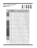
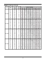
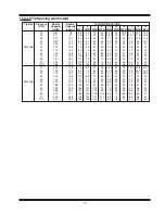
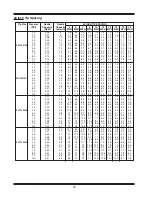
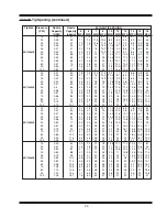
Page 38: ...34 TeeJet Air Induction Spray Tips At Various Speeds And Pressures 20 Inch Tip Spacing...
Page 94: ......
Page 96: ...2007 by Miller St Nazianz Inc...

