OM-222166 Page 27
SECTION 7 − SETUP AND OPERATION
7-1.
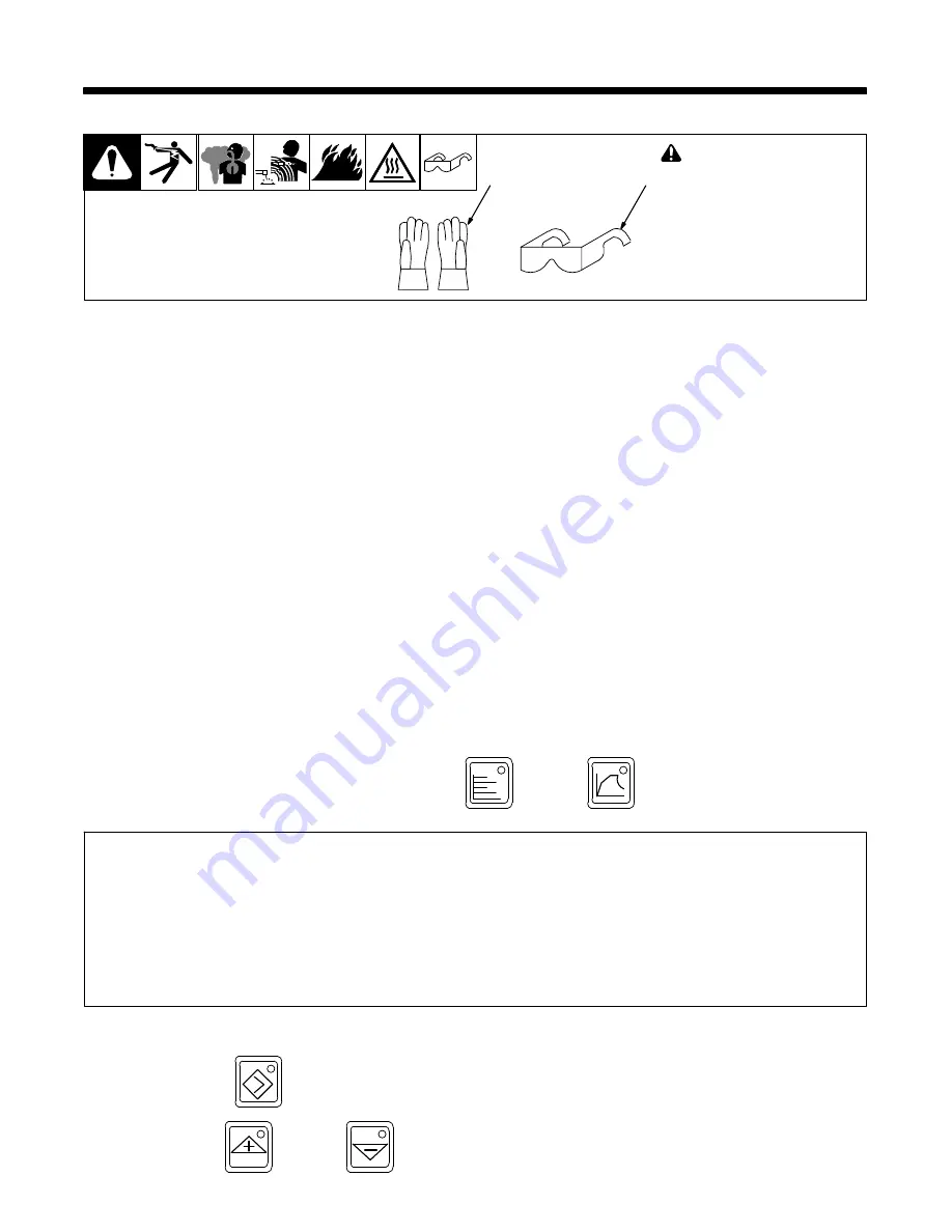
Safety Equipment
!
Do not wear rings or watches
during operation.
Wear the following during
operation:
1
Dry, Insulating Gloves
2
Safety Glasses With Side
Shields
sb3.1* 1/94
1
2
7-2.
System Description
The ProHeat 35 Induction Heating Power Source is designed to function either as an air-cooled system or a liquid-cooled system. Depending on the
system type (including Air-cooled, Liquid-cooled, and Rolling Inductor), the power source is automatically configured to operate and provide an output
appropriate for the type of connected heating device.
A special identifier, embedded within the extension cable connector, provides the means for the power source to configure itself by recognizing the type
of extension cable(s) attached to its output connectors.
Designed to provide a single level of output (up to 35 kW), the ProHeat 35 power source has two panel mounted connectors that are connected in
parallel to the power source output. This design allows the system to operate with either a single output extension cable or two output extension cables.
If a single output extension cable is used, a protective plug (provided with the system) MUST be placed on the unused output connector or the system
will not operate. If two output extension cables are used, they both MUST be of the same type (either both air-cooled or both liquid-cooled) or the system
will not operate (in this case, the protective plug is not used). When two extension cables and heating devices are utilized on the system, the extension
cable lengths and heating devices MUST be identical (see Section 5-7).
The ProHeat 35 is intelligent to the point that it will automatically adjust output power levels if internal system operating parameters or internal tempera-
tures reach or exceed specific set limits (see Section 10).
7-3.
Important System Guidelines
NOTICE − When using multiple ProHeat systems on the same workpiece, keep the the coil(s) from each system at least 1 ft (30 cm) apart. The ProHeat
35 may be damaged if coils are placed closer together.
NOTICE − Some residual heating can occur in ferrous materials placed near the output cables. Moving the output cables away from the ferrous materi-
als could reduce inadvertent heating.
Non−ferrous materials can be used for fixturing depending on part temperature. Examples include glastic, pegboard, wood, PVC, and fiberglass. If
metallic materials need to be used, consider limited amounts of aluminum, brass, or copper.
7-4.
Power Source/System Setup
To view the System Setup screen, simultaneously press the Parameters
Hz
V
A
kW
and Program
buttons and the following screen will appear
on the display:
Deg Units...:>
_
F SYSTEM SETUP1
Tolerance...:
±
25
Max Output..: 35 KW RI Clr Purge: 60s
Control Mode: Temp RI Init KW: 0.0KW
System Setup Screen 1
To change a setting:
S
Press the Cursor
button to move the cursor to the parameter to be changed.
S
Press Increase
or Decrease
button to select desired set-up feature.


