background image

OM-244 023 Page 38

SECTION 8 

 ENGINE/GENERATOR MAINTENANCE

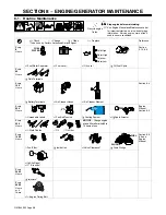
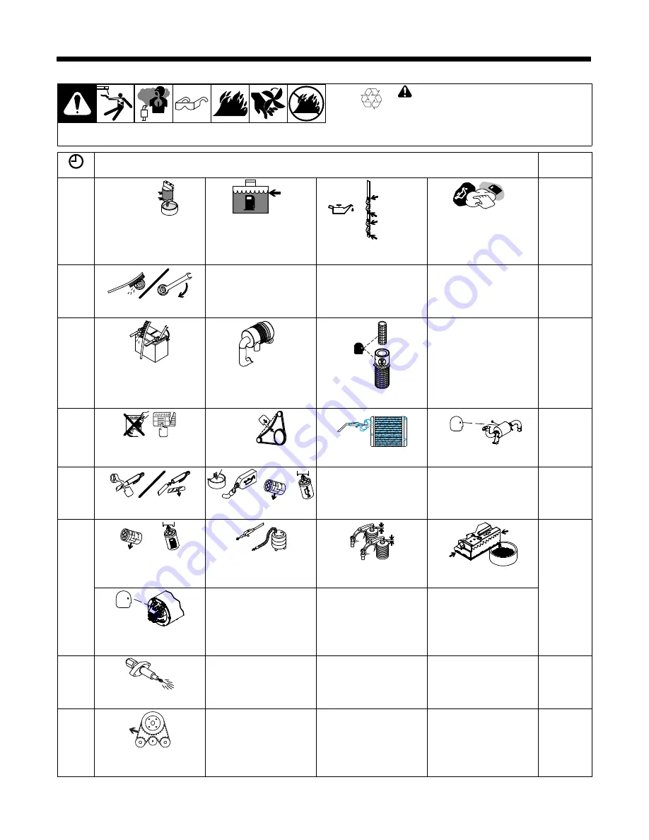
8-1. Routine Maintenance

!

Stop engine before maintaining.

See  Engine Manual and Maintenance Label
for important start-up, service, and storage

information.  Service engine more often if

used in severe conditions.

Recycle engine

fluids.

 = Check

 = Change

 = Clean

 = Replace

* To be done by Factory Authorized Service Agent

Reference

Every

8

Hours

FUEL

WATER

Cold High

Cold Low

Warm High

Warm Low

Section

5-10, 8-8

 Fuel/Water Separator

 Fuel Level

 Oil Level

 Oil, Fuel Spills

Every

50

Hours

 Weld Terminals

Every

100

Hours

Section 8-4

 Battery Terminals

 Air Cleaner Hoses

 Air Cleaner Element

Every

250

Hours

1/2 in.

(13 mm)

Engine

Manual,

Section 8-5

 Unreadable Labels

 Fan Belt Tension

 Cooling System

Spark Arrestor

Every

500

Hours

NOTICE 

 Change engine

oil and filter after initial 50 to

75 hours of use.

 Weld Cables

 Oil

 Oil Filter

Every

1000

Hours

OR

SLUDGE

FUEL

Section 8-8,

8-6 and

Engine

Manual

 Fuel Filter

 Inside Unit

Valve Clearance*

 Drain Sludge

 Slip Rings*


Brushes*

Every

3000

Hours

 Injectors*

Every

6000

Hours

or 5

Years

 Engine Timing Belt

Summary of Contents for Big Blue 800

Page 1: ... Arc CAC A Cutting and Gouging Stick SMAW Welding MIG GMAW Welding Flux Cored FCAW Welding Engine Driven Welding Generator OM 244 023B 2011 03 21 TIG GTAW Welding Big Blue 800 Visit our website at www MillerWelds com File Engine Drive ...

Page 2: ...ontinue the tradition They re just as committed to providing equipment and service that meets the high standards of quality and value established in 1929 This Owner s Manual is designed to help you get the most out of your Miller products Please take time to read the Safety precautions They will help you protect yourself against potential hazards on the worksite We ve made installation and operati...

Page 3: ...ecifications 17 4 2 Sound Level Table 17 4 3 Dimensions Weights And Operating Angles 17 4 4 Stick And MIG Volt Ampere Curves 18 4 5 DC TIG Volt Ampere Curves 19 4 6 Fuel Consumption 19 4 7 Generator AC Power Curve 20 SECTION 5 INSTALLATION 21 5 1 Serial Number And Rating Label Location 21 5 2 Installing Welding Generator 21 5 3 Mounting Welding Generator 22 5 4 Grounding Generator To Truck Or Trai...

Page 4: ...ing Generator Brushes 42 8 7 Engine Speed Adjustment 42 8 8 Servicing Engine Fuel And Lubrication Systems 43 8 9 Engine Generator Overload Protection 44 SECTION 9 TROUBLESHOOTING 45 9 1 Troubleshooting Tables 45 SECTION 10 ELECTRICAL DIAGRAM 48 SECTION 11 RUN IN PROCEDURE 50 11 1 Wetstacking 50 11 2 Run In Procedure Using Load Bank 51 11 3 Run In Procedure Using Resistance Grid 52 SECTION 12 GENER...

Page 5: ...ing or when there is a high risk of unavoid able or accidental contact with the workpiece or ground For these conditions use the following equipment in order presented 1 a semiautomaticDC constant voltage wire welder 2 a DC manual stick welder or 3 an AC welder with reduced open circuit volt age In most situations use of a DC constant voltage wire welder is recommended And do not work alone Discon...

Page 6: ...n easily go through small cracks and openings to adjacent areas Watch for fire and keep a fire extinguisher nearby Be aware that welding on a ceiling floor bulkhead or partition can cause fire on the hidden side Do not weld on closed containers such as tanks drums or pipes unless they are properly prepared according to AWS F4 1 see Safety Standards Do not weld where the atmosphere may contain flam...

Page 7: ...PARTS can injure Keep away from moving parts such as fans belts and rotors Keep all doors panels covers and guards closed and securely in place Stop engine before installing or connecting unit Have only qualified persons remove doors panels covers or guards for maintenance and troubleshooting as necessary To prevent accidental starting during servicing disconnect negative battery cable from batter...

Page 8: ...G PARTS can injure Keep away from moving parts such as fans belts and rotors Keep all doors panels covers and guards closed and securely in place Keep hands hair loose clothing and tools away from moving parts Before working on hydraulic system turn off and lockout tagout unit release pressure and be sure hydraulic pressure cannot be accidentally applied Have only qualified people remove guards or...

Page 9: ... PARTS can burn Do not touch hot compressor or air system parts Allow cooling period before working on equip ment To handle hot parts use proper tools and or wear heavy insu lated welding gloves and clothing to prevent burns READ INSTRUCTIONS Read and follow all labels and the Owner s Manual carefully before installing operating or servicing unit Read the safety information at the beginning of the...

Page 10: ... frequency source doors and panels tightly shut keep spark gaps at correct setting and use grounding and shielding to minimize the possibility of interference ARC WELDING can cause interference Electromagnetic energy can interfere with sensitive electronic equipment such as micro processors computers and computer driven equipmentsuch as robots Be sure all equipment in the welding area is electroma...

Page 11: ...r General Indus try Title 29 Code of Federal Regulations CFR Part 1910 Subpart Q and Part 1926 Subpart J from U S Government Printing Office Super intendentof Documents P O Box 371954 Pittsburgh PA 15250 7954 phone 1 866 512 1800 there are 10 OSHA Regional Offices phone for Region 5 Chicago is 312 353 2220 website www osha gov U S Consumer Product Safety Commission CPSC 4330 East West Highway Beth...

Page 12: ...de télécommande si l appareil en est équipé Des précautions de sécurité supplémentaires sont requises dans des environnements à risque comme les endroits humides ou lorsque l on porte des vêtements mouillés sur des structures mé talliques au sol grillages et échafaudages dans des positions assises à genoux et allongées ou quand il y a un risque important de contact accidentel avec la pièce ou le s...

Page 13: ...s normes de sécurité Porter des lunettes de sécurité avec écrans latéraux même sous votre casque Avoir recours à des écrans protecteurs ou à des rideaux pour protéger les autres contre les rayonnements les éblouissements et les étincelles prévenir toute personne sur les lieux de ne pas regarder l arc Porter des vêtements confectionnés avec des matières résistan tes et ignifuges cuir coton lourd ou...

Page 14: ...s Débrancher le câble négatif en premier lieu Le rebrancher en dernier lieu Les sources d étincelles flammes nues cigarettes et autres sources d inflammation doivent être maintenues à l écart des batteries Ces dernières produisent des gaz explosifs en fonctionnementnormal et en cours de charge Respecter les consignes du fabricant de la batterie pour travailler sur une batterie ou à proximité Le CO...

Page 15: ... nominal ou la capacité de la pompe hydraulique ou de tout équipement du circuit hydraulique Concevoir le circuit hydraulique de telle sorte que la défaillance d un composant hydraulique ne risque pas de provoquer un accident matériel ou corporel Avant d intervenir sur le circuit hydraulique couper l alimentation électrique verrouiller et étiqueter l appareil détendre la pression et s assurer que ...

Page 16: ...er un accident matériel ou corporel Avant d intervenir sur le circuit d air comprimé couper l alimentation électrique verrouiller et étiqueter l appareil détendre la pression et s assurer que le circuit d air ne peut être mis sous pression par inadvertance Ne pas intervenir sur le circuit d air comprimé lorsque l appareil fonctionne Seul un personnel qualifié est autorisé et appliquant les consign...

Page 17: ... appareil à proximité de pro duits inflammables Ne pas surcharger l installation électrique s assurer que l ali mentationest correctement dimensionnée et protégée avant de mettre l appareil en service LA CHUTE DE L ÉQUIPEMENT peut provoquer des blessures Utiliser l anneau de levage pour lever l appareil et les accessoires correctement installées seuls PAS les bouteilles de gaz Ne pas dé passer le ...

Page 18: ...nsible tel que les ordinateurs et l équipementcommandé par ordinateur tel que les robots Veiller à ce que tout l équipement de la zone de soudage soit compatibleélectromagnétiquement Pour réduire la possibilité d interférence maintenir les câbles de soudage aussi courts que possible les grouper et les poser aussi bas que possible ex par terre Veiller à souder à une distance de 100 mètres de tout é...

Page 19: ...bpart J from U S Government Printing Office Super intendentof Documents P O Box 371954 Pittsburgh PA 15250 7954 phone 1 866 512 1800 there are 10 OSHA Regional Offices phone for Region 5 Chicago is 312 353 2220 website www osha gov U S Consumer Product Safety Commission CPSC 4330 East West Highway Bethesda MD 20814 phone 301 504 7923 website www cpsc gov Applications Manual for the Revised NIOSH L...

Page 20: ...ic Engine Oil Check Injectors Pump Check Valve Clearance Fuel Engine Coolant Temperature Positive Negative Wire Feed Welding Arc A Amperes V Volts Panel Local Remote Output Direct Current DC Alternating Current AC Gas Tungsten Arc Welding TIG Stick SMAW Welding Constant Current CC MIG GMAW Welding Constant Voltage CV 3 Three Phase 1 Single Phase Air Carbon Arc Cutting CAC A Protective Earth Ground...

Page 21: ... at 23 ft 7 m 78 5 dBA 3 3 ft 1 m from front panel 102 2 Lwa sound power 74 1 dBa at 23 ft 7 m 81 9 dBA 3 3 ft 1 m from front panel 104 8 Lwa sound power 76 0 dBa at 23 ft 7 m 85 2 dBA 3 3 ft 1 m from front panel 4 3 Dimensions Weights And Operating Angles Dimensions 802 161 A Front Panel End D B A F E H G C Do not exceed tilt angles or engine could be damaged or unit could tip Do not move or oper...

Page 22: ... capabilities of the welding generator Curves of all other settings fall between the curves shown B MIG Mode A DC Stick Mode 0 20 40 60 80 100 0 100 200 300 400 500 600 700 800 900 1000 1100 1200 D CV O LTS D CA M P ER E S Ranges 300 M ax 185 525 125 400 85 250 0 20 40 60 80 100 0 100 200 300 400 500 600 700 800 900 1000 1100 1200 D CVO LTS D CA M PER ES ...

Page 23: ...f all other settings fall between the curves shown 0 20 40 60 80 100 0 100 200 300 400 500 600 700 D CVO LTS D CAMPERES 4 6 Fuel Consumption The curve shows typical fuel use under weld or generator power loads Ref 240 053 A 0 00 0 25 0 50 0 75 1 00 1 25 1 50 1 75 2 00 2 25 2 50 2 75 3 00 0 50 100 150 200 250 300 350 400 450 500 550 600 DC WELD AMPERES AT 100 DUTY CYCLE US Gal Hr Idle ...

Page 24: ... 054 A The ac power curve shows the gen erator power in amperes available at the 120 and 240 volt receptacles 0 50 100 150 200 250 300 0 5 10 15 20 25 30 AC AMPERES IN 240V MODE AC VOLTS 0 25 50 75 100 150 125 0 10 20 30 40 50 60 AC AMPERES IN 120V MODE ...

Page 25: ...not move or operate unit where it could tip Always securely fasten weld ing generator onto transport vehicle or trailer and comply with all DOT and other applica ble codes NOTICE Do not install unit where air flow is restricted or engine may overheat See Section 4 3 for lifting eye rating See Section 5 3 for mounting in formation install3 2008 01 Ref 800 652 Ref 800 477 A 803 274 804 712 18 in 460...

Page 26: ...ss Supports 2 Mounting Brackets Supplied Mount unit on flat surface or use cross supports to support base Secure unit with mounting brack ets 3 1 2 in Bolt And Washer Minimum Not Supplied 4 3 8 16 x 1 in Screws Supplied To Bolt Unit In Place Remove hardware securing the four mounting brackets to the base Reverse brackets and reattach to base with original hardware Mount unit to truck or trailer wi...

Page 27: ...und wire from the generator equip ment grounding terminal to bare metal on the vehicle frame as shown If unit does not have GFCI re ceptacles use GFCI pro tected extension cord 1 Equipment Grounding Terminal On Front Panel 2 Grounding Cable Not Supplied 3 Metal Vehicle Frame Connect cable from equipment ground terminal to metal vehicle frame Use 10 AWG or larger insulated copper wire Electrically ...

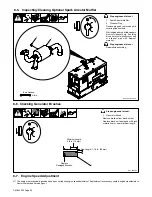
Page 28: ...ling Optional Spark Arrestor Muffler Tools Needed Stop engine and let cool 1 Spark Arrestor Muffler 2 Double Flanged Elbow 3 Nut 4 Flat Washer 5 Mount 6 Bracket 7 Screw 8 Single Flanged Elbow 9 Rain Cap 10 Clamp Loosely assemble components as shown Mount the muffler with the clean out plug to the outside After assembly final tighten all clamps and hardware Be sure to tighten rain cap mounting scre...

Page 29: ...cessary add electro lyte to raise to proper level Reins tall vent caps 4 Battery Charger Read and follow all instruc tions supplied with battery charger 5 5 Amperes For 30 Minutes Charge Time 6 30 Amperes For 12 Minutes Charge Time Charge battery Disconnect charg ing cables and install battery When electrolyte is low add only distilled water to cells to maintainproper level 1 Tools Needed 2 4 3 dr...

Page 30: ...nect Switch The battery disconnect switch dis connects battery voltage from the circuit When the switch is turned Off the front panel controls do not work To run unit turn switch to On posi tion To prevent unit from running turn switch to Off position The switch may be locked using a customer suppliedpadlock 1 OFF ON ...

Page 31: ...engine maintenance label for fuel specifica tions Leave filler neck empty to allow room for expansion Engine stops if fuel level is low Engine Oil After fueling check oil with unit on level sur face Oil level on a cold engine should be between cold low and cold high indicators on dipstick Oil level on a warm engine should be between warm high and warm low indicators on dipstick Add oil if neces sa...

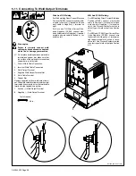
Page 32: ... Output Terminal Ref 803 452 803 778 B Tools Needed 3 4 in MIG And FCAW Welding For MIG welding Direct Current Electrode Positive DCEP connect wire feeder cable to Positive terminal on left and work cable to Negative terminal on right Use Process Contactor switch to select type of weld output see Section 6 3 For MIG and FCAW Direct Current Elec trode Negative DCEN connect wire feeder cable to Nega...

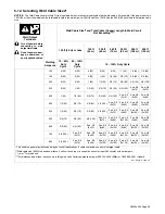
Page 33: ...a 2 0 2x70 2 ea 2 0 2x70 300 1 50 1 0 60 2 0 70 3 0 95 4 0 120 2 ea 2 0 2x70 2 ea 3 0 2x95 2 ea 3 0 2x95 350 1 0 60 2 0 70 3 0 95 4 0 120 2 ea 2 0 2x70 2 ea 3 0 2x95 2 ea 3 0 2x95 2 ea 4 0 2x120 400 1 0 60 2 0 70 3 0 95 4 0 120 2 ea 2 0 2x70 2 ea 3 0 2x95 2 ea 4 0 2x120 2 ea 4 0 2x120 500 2 0 70 3 0 95 4 0 120 2 ea 2 0 2x70 2 ea 3 0 2x95 2 ea 4 0 2x120 3 ea 3 0 3x95 3 ea 3 0 3x95 600 3 0 95 4 0 12...

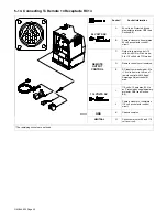
Page 34: ...trol 10 volts dc in MIG or Stick mode 0 to 10 volts dc in TIG mode D Remote control circuit common E DC input command signal 0 to 10 volts from min to max of remote control with Voltage Amperage Adjust control at max 115 VOLTS AC I 115 volts 10 amperes 60 Hz ac Protected by supplementary protector CB6 see Section 8 9 J Contact closure to I completes 115 volt ac contactor control circuit GND K Chas...

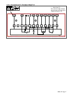
Page 35: ...al Strip T10 There are two bushings on the aux iliary power panel through which leads can be routed to T10 1 A B E K J EQUIPMENT GROUND 11 5 VA C 24 VAC NEUTRAL 1K 093727 00 11219 NEG YELLOW BROWN PURPLE BLUE ORANGE PINK RED BLACK POS YELLOW GREEN YELLOW GREEN NEG POS ...

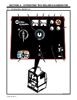
Page 36: ...OM 244 023 Page 32 SECTION 6 OPERATING THE WELDING GENERATOR 6 1 Controls See Section 6 2 803 454 239 132 A 7 10 1 8 11 12 9 5 6 2 3 4 ...

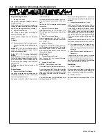
Page 37: ...tage and moni tor the engine charging system The meter should read about 14 volts dc when the en gine is running and about 12 volts dc when the engine is stopped Weld Controls 7 Process Contactor Switch See Section 6 3 for Process Contactor switch information 8 Ampere Range Switch NOTICE Do not switch under load Use switch to select weld amperage range Use all five ranges for Stick welding and the...

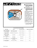
Page 38: ... Stick position the arc drive dig circuit provides addition al amperage during low voltage short arc length conditions to prevent stick ing electrodes The arc drive dig circuit is disabled when switch is in MIG or TIG positions The engine auto idle option does not work in the Remote On Off Switch Required TIG mode Process Contactor Switch Settings Switch Setting Process Output On Off Control Engin...

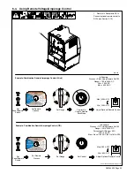
Page 39: ... DC Min 125 A DC Max 400 A DC Adjust Optional Remote Control Set Panel Remote Switch Set Range Control Not Used In Remote Stick Mode Max 400 A DC Min 125 A DC Set Remote Process Example Combination Remote Amperage Control TIG In Example Process TIG Using Remote On Off Range 40 to 330 A DC Percentage Of Range 50 Min 40 A DC Max About 185 A DC 50 of 40 to 330 Adjust Optional Remote Control Set Range...

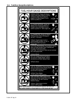
Page 40: ...OM 244 023 Page 36 6 5 Fuel Hour Gauge Descriptions ...

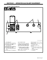
Page 41: ...wer speed If a ground fault is detected receptacle Re set button pops out and receptacle does not work Check for faulty tools plugged into re ceptacle Press button to reset receptacle At least once a month run engine at weld power speed and press test but ton to verify GFCI is working properly Maximum output is 2 4 kVA kW from each GFCI and 4 kVa kW from RC1 Maximum combined output of all recep ta...

Page 42: ...ection 5 10 8 8 Fuel Water Separator Fuel Level Oil Level Oil Fuel Spills Every 50 Hours Weld Terminals Every 100 Hours Section 8 4 Battery Terminals Air Cleaner Hoses Air Cleaner Element Every 250 Hours 1 2 in 13 mm Engine Manual Section 8 5 Unreadable Labels Fan Belt Tension Cooling System Spark Arrestor Every 500 Hours NOTICE Change engine oil and filter after initial 50 to 75 hours of use Weld...

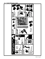
Page 43: ...OM 244 023 Page 39 8 2 Engine Maintenance Label ...

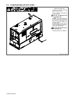
Page 44: ...ater plug to receptacle Do not run engine while oil pan heater is on NOTICE In extremely cold weath er heater should be connected to power source when engine oil is warm to eliminate possibility of oil coking on heater Severe coking on heater element may cause damage to engine en gine oil and oil pan heater The area near the the oil pan heater gets hot Disconnect plug to turn off heater 1 ...

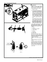
Page 45: ...additional engine protection Never clean a safety element Re place the safety element after servic ing the primary element three times Clean or replace primary element if dirty see note above before cleaning Re place primary element if damaged Re place primary element yearly or after six cleanings 2 Housing 3 Safety Element Optional 4 Primary Element 5 Dust Cap 6 Dust Ejector To clean air filter W...

Page 46: ...erial Stop engine and let cool Reinstall cleanout plug Tools Needed 3 8 in 1 2 8 6 Checking Generator Brushes Ref 206 467 Stop engine and let cool 1 Generator Brush Remove brushes from brush holder Replace brushes if damaged or if brush material is at or near minimum length 1 Damaged Brushes New Length 1 1 4 in 32 mm Minimum Length 5 8 in 16 mm Replace 8 7 Engine Speed Adjustment The engine is ele...

Page 47: ...place primary fuel filter Turn filter counterclockwise Remove filter Apply thin coat of fuel to gasket on new filter Fill filter with fuel Install filter and turn clock wise until tight Bleed air from fuel system according to engine manual Inspect fuel lines and replace if cracked or worn To replace secondary fuel filter See engine manual Close doors To drain sludge from fuel tank Beware of fire D...

Page 48: ...tically resets when the fault is corrected CB5 protects the 24 volt ac output to re mote receptacle RC14 and 24 volt out put to field current regulator board PC1 If CB5 opens weld output and 24 volt output to RC14 stops On units with op tional power plant power at receptacle RC5 also stops if CB5 opens CB6 protects the 115 volt ac output to remote receptacle RC14 If CB6 opens 115 volt output to RC...

Page 49: ... output Check and tighten connections inside and outside unit Be sure connection to work piece is clean and tight Use dry properly stored electrodes Remove excessive coils from weld cables Have Factory Authorized Service Agent check brushes and slip rings High weld output Check position of Ampere Range switch and Voltage Amperage Adjust control Engine speed may need adjustment Contact engine manuf...

Page 50: ...ve Factory Authorized Service Agent check integrated rectifier SR1 capacitor C9 diode capacitor board D1 C1 and the rotor Reset supplementary protectors CB12 Have Factory Authorized Service Agent check field current regu lator board PC1 see Section 8 9 Have Factory Authorized Service Agent check brushes and slip rings and field excitation circuit High output at generator power receptacles Engine s...

Page 51: ...l fuel can gel in cold weather Contact local fuel supplier for fuel information Use correct grade oil for cold weather see Section 8 2 Engine suddenly stops Check fuel level Optional low fuel shutdown stops engine if fuel level is low Check oil level Automatic shutdown system stops engine if oil pressure is too low or engine temperature is too high see Section 5 10 Have Factory Authorized Service ...

Page 52: ...OM 244 023 Page 48 SECTION 10 ELECTRICAL DIAGRAM Figure 10 1 Circuit Diagram For Welding Generator ...

Page 53: ...OM 244 023 Page 49 244 022 B ...

Page 54: ...ings seat faster if engine runs at weld power rpm and the welding generator is kept loaded during run in 2 Engine Exhaust Pipe Wetstacking is unburned fuel and oil in the exhaust pipe and occurs during run in if the engine is run too long at light load or idle rpm If exhaust pipe is coated with a wet black tar like substance dry the engine using one of the following run in procedures See the engin...

Page 55: ...enerator weld output terminals using proper size weld cables with correct connectors Observe correct polarity Start engine and run for several minutes Set load bank switches and then adjust generator A V control so load equals rated voltage and current of generator see name plate rating label or the specifi cations section in this manual Check generator and load bank meters after first five minute...

Page 56: ...c tors polarity is not important 4 Voltmeter 5 Clamp On Ammeter Connect voltmeter and ammeter as shown if not provided on generator Start engine and run for several minutes Set grid switches and then ad just generator A V control so load equals rated voltage and current of the generator see nameplate rating label or the specifications section in this manual Check generator and meters after first f...

Page 57: ...hock and static electricity hazards Also see AWS Safety Health Fact Sheet No 29 Grounding of Portable And Vehicle Mounted Welding Generators 1 EquipmentGrounding Terminal On Front Panel 2 Grounding Cable Not Supplied 3 Metal Vehicle Frame Connect cable from equipment ground terminal to metal vehicle frame Use 8 AWG or larger insu lated copper wire Electrically bond generator frame to vehicle frame...

Page 58: ...ve load and requires a constant amount of power 2 Non Resistive Load Equipment with a motor is a non re sistive load and requires approxi mately six times more power while starting the motor than when running see Section 12 8 3 Rating Data Rating shows volts and amperes or watts required to run equipment Amperes x Volts Watts Example 1 If a drill uses 4 5 am peres at 115 volts calculate its run ni...

Page 59: ...m Home Equipment Rating Starting Watts Running Watts Stock Tank De Icer 1000 1000 Grain Cleaner 1 4 HP 1650 650 Portable Conveyor 1 2 HP 3400 1000 Grain Elevator 3 4 HP 4400 1400 Milk Cooler 2900 1100 Milker Vacuum Pump 2 HP 10500 2800 FARM DUTY MOTORS 1 3 HP 1720 720 Std e g Conveyors 1 2 HP 2575 975 Feed Augers Air 3 4 HP 4500 1400 Compressors 1 HP 6100 1600 1 1 2 HP 8200 2200 2 HP 10550 2850 3 ...

Page 60: ...1 HP 6000 1500 1 1 2 HP 8200 2200 2 HP 10500 2800 Electric Chain Saw 1 1 2 HP 12 in 1100 1100 2 HP 14 in 1100 1100 Electric Trimmer Standard 9 in 350 350 Heavy Duty 12 in 500 500 Electric Cultivator 1 3 HP 2100 700 Elec Hedge Trimmer 18 in 400 400 Flood Lights HID 125 100 Metal Halide 313 250 Mercury 1000 Sodium 1400 Vapor 1250 1000 Submersible Pump 400 gph 600 200 Centrifugal Pump 900 gph 900 500...

Page 61: ...t must be at least twice the motor s running amperage kVA HP x HP x 1000 Volts Starting Amperage Example Calculate starting amper age required for a 230 V 1 4 HP mo tor with a motor start code of M Volts 230 HP 1 4 kVA HP 11 2 11 2 x 1 4 x 1000 230 12 2A Starting the motor requires 12 2 amperes VOLTS AMPS HP 230 2 5 1 4 Hz PHASE CODE 60 1 M AC MOTOR 1 2 3 4 12 9 How Much Power Can Generator Supply...

Page 62: ...ck to electric utility when service is re stored Install correct switch customer supplied Switch rating must be same as or greater than the branch overcurrent protection 3 Fused Disconnect Switch Install correct switch customer supplied if required by electrical code 4 Welding Generator Output Generator output voltage and wir ing must be consistent with regular utility system voltage and wiring Co...

Page 63: ...50 15 40 4800 112 34 62 19 37 11 45 5400 100 30 62 19 50 6000 87 26 50 15 Conductor size is based on maximum 2 voltage drop Cord Lengths for 240 Volt Loads If unit does not have GFCI receptacles use GFCI protected extension cord Maximum Allowable Cord Length in ft m for Conductor Size AWG Current Amperes Load Watts 4 6 8 10 12 14 5 1200 700 213 450 137 225 84 200 61 7 1680 800 244 500 152 300 91 2...

Page 64: ... Hardware is common and not available unless listed 1 2 3 4 5 6 7 8 9 10 11 12 13 13 14 15 16 17 18 19 20 21 22 23 24 25 110 111 112 113 114 115 116 Figure 13 2 117 118 119 120 121 122 Figure 13 3 123 124 125 126 131 Figure 13 1 Main Assembly ...

Page 65: ...0 31 32 33 34 35 36 37 38 39 40 41 43 44 45 46 47 48 49 50 52 51 53 54 55 56 57 58 59 60 61 62 63 64 65 66 67 68 69 70 71 72 73 74 75 76 77 78 79 80 81 82 83 84 85 86 87 88 89 90 91 92 93 94 95 96 97 98 Figure 13 5 99 100 101 102 103 104 105 106 107 108 109 127 128 129 130 ...

Page 66: ... Lift Eye 1 20 209612 Lever Switch Lockout Disconnect Battery 1 21 209597 Bracket Mtg Battery Disconnect Switch 1 22 209611 Switch Disc Battery 2P 6 36 Volts 1 23 196220 Bracket Holddown Fuel Tank Rear 1 24 192362 Bracket Mtg Nyl 1 2 Conduit 1 25 209094 Bracket Mtg Hose 1 26 206603 Cover Top 1 27 189052 Grommet Plastic Neck Filler Fuel 1 28 190198 Cap Tank Screw on 3 500 In W Vent W Lanyard 8 1 29...

Page 67: ...Extension R H 1 67 239505 Guard Fan RH 1 68 225120 Label Warning Moving Parts Can Cause Injury 6 69 208024 Pulley Fan Assy W Bearings 1 70 206613 Bracket Mtg Fan Alternator 1 71 199849 Screw 625 11x4 00 Hex Hd pln Gr5 Pld 4 72 071731 Washer Flat 656idx2 250odx 187t Stl Pld 4 73 191812 Bracket Mtg Engine R h 1 74 071890 Retainer Mount Eng Gen 4 75 071730 Tubing Stl 875 Od X12ga Wall X 2 500 4 76 08...

Page 68: ... Not Use Ether 1 119 182496 Term Assy Pwr Output 2 120 244139 Box Starting Panel Rr 2 121 206609 Upright Front 1 122 Figure 13 3 Panel Front w components 1 123 191448 Cover Top Front Upright 1 124 244086 Main Rectifier Assembly 1 125 PC1 244098 Module Field Current Regulator 1 126 244095 Bracket Mtg Box Fcr 1 127 195746 Sender Coolant Temp 130c Switch 1 128 239641 Ftg Adapter Oil Temperature Sende...

Page 69: ... CR8 197325 Relay Encl 12vdc Spst 70a 4pin Flange Mtg 1 8 CR3 173069 Relay Encl 12vdc Spdt 30a 20a 5pin Flange Mtg 1 9 CR1 252053 Relay Encl 12 vdc spst 35A 14 vdc 5pin 1 10 201079 Cover Control Box 1 11 C1 D1 C8 D8 D12 189701 Diode Capacitor Board 4 12 CB10 CB16 190374 Circuit Breaker Auto Reset 12vdc 40 Amp 2 13 CR5 223710 Relay Encl 12vdc Dpst no 25a 6pin Flange 1 14 SR1 035704 Rectifier Integ ...

Page 70: ... 13h Stl Pld Sem Cone Wshr 38d 4 214876 Relay Encl 6vdc Spst 35a 14vdc 5 Pin 1 139266 Supplementary Protector Man Reset 1p 15a 250vac 1 197325 Relay Encl 12vdc Spst 70a 4pin Flange Mtg 1 148850 Socket Relay 5 Pin 2 240075 Connector Housing Splash Proof 90 Vers 1 240076 Connector Housing Cover 1 240074 Seal Plug Single Wire 5mm Hole 7 240071 Plug Cavity 2 5mm For 5 4mm Dia 18 240098 Connector Housi...

Page 71: ...1 11 12 13 14 15 16 Figure 13 3 Panel Front w Components Description Part No Dia Mkgs Item No Figure 13 3 Panel Front w Components Figure 13 1 Item 122 Quantity 1 239132 Plate Screened Ident Control Order By Model And Serial Number 1 2 238616 Panel Engine Weld Control 1 3 CT3 209274 Xfmr Current Meters 1 4 S3 244087 Switch Range Changeover 1 ...

Page 72: ...witch Lever 1 18 190323 Boot Circuit Breaker Clear Hex Nut 4 19 170391 Conn Circ Ms Protective Cap Size 20 Nylon 1 20 FUEL HM 232112 Gauge Fuel Elec Hour Meter 1 21 BAT 193228 Meter Volt DC 8 18 Scale 2 250 In Black Face 1 22 TEMP 217084 Gauge Coolant Temp 0 300 Deg F 1 23 OIL 217083 Gauge Pressure Oil 0 100 Psi 1 24 A1 164873 Meter Amp AC DC 0 500 0 600 Dc Scale 2 5 In 1 25 V1 164874 Meter Volt A...

Page 73: ... Nut 2 6 083030 Stud Brs 250 20 X 1 750 W Hex Collar 1 7 188719 Block Term 40 Amp 12 Pole Screw Term 1 8 9 10 093996 Supplementary Pro Man Reset 1p 20a 250vac Frict 2 2049100011219 Cable Power 8 C 2 14ga 6 18ga Nspr 11219 1 0937270011219 Label Terminal Strip Cbi 1 When ordering a component originally displaying a precautionary label the label should also be ordered To maintain the factory original...

Page 74: ...ard Generator Wire Mesh 1 9 172674 Spring Ext 240 Od X 041 Wire X 3 500 Pld 2 10 039207 Baffle Air Gen 1 11 ROTOR 210446 Rotor Generator Includes 1 12 024617 Ring Rtng Ext 1 375 Shaft X 050 Thk 1 13 053390 Bearing Ball Rdl Sgl Row 1 370 X 2 830 X 6 1 210447 Fan Rotor Assy Generator Segmented includes 1 14 Hub Drive Not Sold Separately 1 15 210332 Plate Flex Hubmount 1 16 206242 Fan Rotor Segmented...

Page 75: ...lder Generator Brushes Not Included See Item 29 1 31 602242 Washer Flat 375idx0 875odx 083t Stl Pld 2 32 602211 Washer Lock 318idx0 586odx 078t Stl Pld Split 312 2 33 604534 Screw 312 18x1 25 Hex Hd pln Gr5 Pld 2 34 239759 Bracket Mounting Magnetic Pickup Assy 1 When ordering a component originally displaying a precautionary label the label should also be ordered Recommended Spare Parts Optional T...

Page 76: ...OM 244 023 Page 72 Notes Ref AWS ANSI A2 4 Welding Symbols ...

Page 77: ...vers Work Stations Weld Tables No Labor 5 6 Months Parts Batteries Bernard Guns No Labor Tregaskiss Guns No Labor 6 90 Days Parts Accessory Kits Canvas Covers Induction Heating Coils and Blankets Cables and Non Electronic Controls M Guns MIG Guns and Subarc SAW Guns Remote Controls and RFCS RJ45 Replacement Parts No labor Roughneck Guns Spoolmate Spoolguns Miller s True Blue Limited Warranty shall...

Page 78: ...h your personal records Always provide Model Name and Serial Style Number Contact a DISTRIBUTOR or SERVICE AGENCY near you Welding Supplies and Consumables Options and Accessories Personal Safety Equipment Service and Repair Replacement Parts Training Schools Videos Books Technical Manuals Servicing Information and Parts Circuit Diagrams Welding Process Handbooks Contact the Delivering Carrier to ...

Reviews: