OM-246 022 Page 18
SECTION 5
−
ELECTRICAL DIAGRAMS
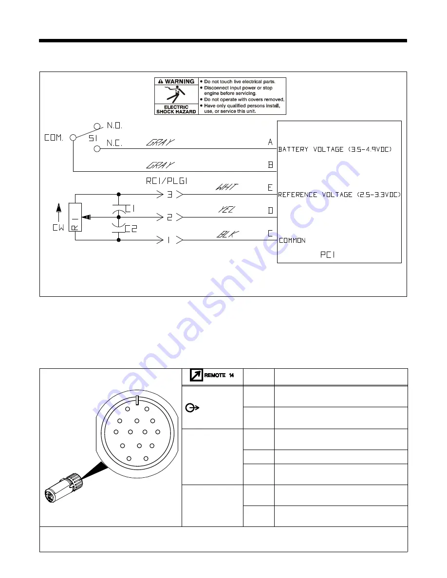
5-1.Foot Control Circuit Diagram
246 020-A
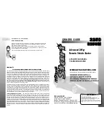
5-2.Receiver 14 Plug Information
A
J
B
K
I
C
L
N
H
D
M
G
E
F
805 483-A
Pin*
Pin Information
OUTPUT
CONTACTOR
A
Supply voltage 10-35 VAC/VDC with respect to
pin D.
B
Activates machine output contactor. Closure from
pin A.
REMOTE
OUTPUT
CONTROL
C
Command supply voltage 0
−
10 VDC with respect
to pin D.
D
Remote control circuit common.
E
Command: percentage of pin C supply voltage
with respect to pin D.
A/V
AMPERAGE
VOLTAGE
F
Current feedback from power source; +1 volt DC
per 100 amperes.
H
Voltage feedback from power source; +1 volt DC
per 10 volts output.
* The remaining pins are not used.


