background image

OM-193471 Page 24

SECTION 6 − OPERATION

6-1.

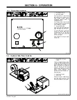
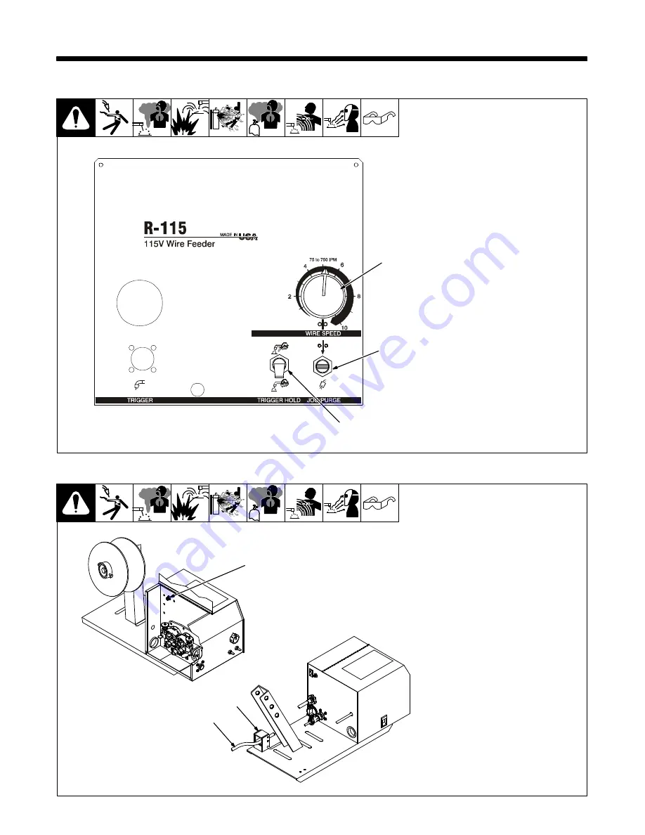
Front Panel Controls

1

Wire Speed Control

2

Jog/Purge Switch

Use Jog position to momentarily
feed welding wire at speed set on
Wire Speed control without
energizing welding circuit or
shielding gas valve.

Use Purge position to momentarily
energize gas valve to purge air from
gun or adjust gas regulator.

3

Trigger Hold Switch

Push up to weld without holding gun
trigger throughout the weld cycle.

To start weld cycle, press and
release gun trigger within three
seconds after an arc has been
struck. To end weld, press and
release gun trigger.

Power switch is on rear panel (see
Section 5-3)

192 510-B

1

2

3

6-2.

Optional Side Panel Controls

Ref. 802 310-B / Ref. 802 309-B

1

Optional Run-In Speed
Control

The Run-In Speed Control provides
a means of selecting the rate at
which welding wire will feed after
preflow and before arc initiation.
After arc initiation, the wire feed
speed is governed by the Wire
Speed Control. Rotating the Run-In
Speed Control clockwise will
increase run-in wire feed speed.

Close side door.

2

Reed Relay Switch

3

Weld Cable

Weld cable must be routed through
reed relay switch present on units
with Run-In Speed Control option.

1

2

3

Summary of Contents for R-115

Page 1: ...Processes Description MIG GMAW Welding Flux Cored FCAW Welding Wire Feeder OM 193471X 2016 10 R 115 File MIG GMAW For product information Owner s Manual translations and more visit www MillerWelds com ...

Page 2: ...ontinue the tradition They re just as committed to providing equipment and service that meets the high standards of quality and value established in 1929 This Owner s Manual is designed to help you get the most out of your Miller products Please take time to read the Safety precautions They will help you protect yourself against potential hazards on the worksite We ve made installation and operati...

Page 3: ...Welding Gun And Weld Cable 16 5 5 Installing Wire Guide And Drive Roll 17 5 6 Installing And Threading Welding Wire 18 5 7 Interconnecting Power Cord Ground Lead Connection All Models 19 5 8 Connection For L TEC Welding Power Sources With 7 Flat Socket Receptacle 19 5 9 Connection For Hobart Welding Power Sources With 19 Socket Receptacle 20 5 10 Connection For L TEC Welding Power Sources With 19 ...

Page 4: ......

Page 5: ...kneeling or lying or when there is a high risk of unavoid able or accidental contact with the workpiece or ground For these conditions use the following equipment in order presented 1 a semiautomaticDC constant voltage wire welder 2 a DC manual stick welder or 3 an AC welder with reduced open circuit volt age In most situations use of a DC constant voltage wire welder is recommended And do not wor...

Page 6: ...pared according to AWS F4 1 and AWS A6 0 see Safety Standards D Do not weld where the atmosphere can contain flammable dust gas or liquid vapors such as gasoline D Connect work cable to the work as close to the welding area as practical to prevent welding current from traveling long possibly unknown paths and causing electric shock sparks and fire hazards D Do not use welder to thaw frozen pipes D...

Page 7: ...TS can injure D Keep away from moving parts such as fans D Keep all doors panels covers and guards closed and securely in place D Have only qualified persons remove doors panels covers or guards for maintenance and troubleshooting as necessary D Reinstall doors panels covers or guards when maintenance is finished and before reconnecting input power READ INSTRUCTIONS D Read and follow all labels an...

Page 8: ...FPA Standard 51B from National Fire Protection Association Quincy MA 02269 phone 1 800 344 3555 website www nfpa org OSHA Occupational Safety and Health Standards for General Indus try Title 29 Code of Federal Regulations CFR Part 1910 Subpart Q and Part 1926 Subpart J from U S Government Printing Office Super intendentof Documents P O Box 371954 Pittsburgh PA 15250 7954 phone 1 866 512 1800 there...

Page 9: ...ement humideou si l on porte des vêtements mouillés sur des structures métalliquestelles que sols grilles ou échafaudages en position coincée comme assise à genoux ou couchée ou s il y a un risque élevé de contact inévitable ou accidentel avec la pièce à souder ou le sol Dans ces conditions utiliser les équipements suivants dans l ordre indiqué 1 un poste à souder DC à tension constante à fil 2 un...

Page 10: ...udes et des équipements chauds peut provoquer des incen dies et des brûlures Le contact accidentel de l électrode avec des objets métalliques peut provoquer des étincelles une explosion un sur chauffement ou un incendie Avant de commencer le soudage vérifier et s assurer que l endroit ne présente pas de danger D Déplacer toutes les substances inflammables à une distance de 10 7 m de l arc de souda...

Page 11: ... capacité suffisante pour lever l appareil D En utilisant des fourches de levage pour déplacer l unité s assurer que les fourches sont suffisamment longues pour dépasser du côté opposé de l appareil D Tenir l équipement câbles et cordons à distance des véhicules mobiles lors de toute opération en hauteur D Suivre les consignes du Manuel des applications pour l équation de levage NIOSH révisée Publ...

Page 12: ...m bustibles American Welding Society Standard AWS A6 0 from Global EngineeringDocuments phone 1 877 413 5184 website www global ihs com National Electrical Code NFPA Standard 70 from National Fire Protec tion Association Quincy MA 02269 phone 1 800 344 3555 website www nfpa org and www sparky org Safe Handling of Compressed Gases in Cylinders CGA Pamphlet P 1 from Compressed Gas Association 14501 ...

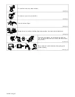
Page 13: ...n Safe37 2012 05 Safe57 2012 05 Wear dry insulating gloves Do not touch electrode wire with bare hand Do not wear wet or damaged gloves Protect yourself from electric shock by insulating yourself from work and ground Safe58 2012 06 Disconnect input plug or power before working on machine Safe5 2012 05 Keep your head out of the fumes Safe59 2012 05 Use forced ventilation or local exhaust to remove ...

Page 14: ... 05 Welding wire and drive parts are at welding voltage during operation keep hands and metal objects away Safe33 2012 05 Wear hat and safety glasses Use ear protection and button shirt collar Use welding helmet with correct shade of filter Wear complete body protection Safe66 2012 06 Become trained and read the instructions before working on the machine or welding Safe65 2012 06 ...

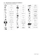
Page 15: ... Instructions A Amperes V Volts Direct Current DC Hz Hertz Set Up Increase Process Time Postflow Time Gas Input Percent Purge By Gas Constant Voltage I2 Rated Welding Current Program IP Degree Of Protection Variable Inductance Preflow Time Line Connection U2 Conventional Load Voltage Wire Feed Cold Jog Inch Towards Workpiece Circuit Breaker Trigger Hold On Sequence Gas Type Trigger Control Three P...

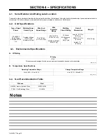
Page 16: ...ts AC Single Phase 2 Amperes 50 60 Hz Constant Voltage CV DC And Contactor Control 75 to 750 ipm 1 9 To 19 mpm 030 To 3 32 in 0 8 To 2 4 mm Max Spool Weight 60 lb 27 kg 100 Volts 500 Amperes 100 Duty Cycle Length 23 1 2 in 597 mm Width 10 3 4 in 273 mm Height 11 in 279 mm 40 lb 18 kg 4 3 Environmental Specifications A IP Rating IP Rating IP2X This equipment is designed for indoor use and is not in...

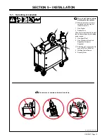
Page 17: ...its cylinder Wire feeder shown is repre sentative only and may not reflect actual unit 1 Wire Feeder 2 Rubber Feet Choose slot that allows all rubber feet to sit securely on top of welding power source 3 Wire Spool Reel 4 Gas Cylinder w Hose And Regulator Customer Supplied Shielding gas pressure not to exceed 100 psi 689 kPa 5 Welding Power Source 6 Running Gear 1 3 5 4 2 6 ...

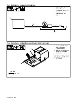
Page 18: ...ion Diagrams 4 3 2 1 1 Gas Hose With 5 8 18 Right hand Thread Fittings Customer Supplied Shielding gas pressure not to exceed 100 PSI 689 kPa 2 Strain Relief Install interconnecting cord to make connection to welding power source see Section 5 7 3 Power Switch 5 3 Rear Panel Connections And Power Switch Location 802 309 B Tools Needed 1 2 3 5 8 11 16 in ...

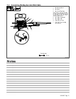
Page 19: ...nto block Position outlet wire guide as close as possible to drive rolls without touching Tighten knob 4 Gun Trigger Receptacle 5 Gun Trigger Plug 6 Weld Cable Terminal 7 Weld Cable From Welding Power Source 5 4 Connecting Welding Gun And Weld Cable 802 308 B 1 3 Tools Needed 9 16 in 2 4 5 7 6 Notes ...

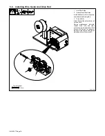
Page 20: ...nlet wire guide and intermediate wire guide 3 Drive Roll 4 Install drive rolls and turn drive roll nut one click During maintenance intervals remove drive rolls and clean grooves using a wire brush Check groove of drive roll for pitting or increase in the depth of the groove indicating drive roll is worn out Tools Needed 3 8 in 1 3 2 ...

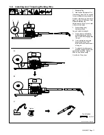
Page 21: ...on nut so wire is taut when wire feed stops 3 Pressure Assembly Adjustment Knob Lay gun cable out straight A Open pressure assemblies hold wire tightly and cut off end Push wire through guides into gun B Close and tighten pressure assemblies Press JOG button until the wire comes out of the gun C To adjust drive roll pressure press gun trigger to feed wire against wood surface Tighten knob so wire ...

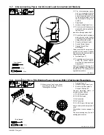
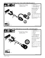
Page 22: ...to chassis ground stud 6 Terminal Block 1T For welding power sources re quiring dry contact closure move lead 38 at terminal block to terminal D Refer to Sections 5 8 through 5 15 and make additional connections to terminal block 1T according to the applicable procedure Tools Needed 1 4 in 3 8 in 1 4 2 5 3 6 5 8 Connection For L TEC Welding Power Sources With 7 Flat Socket Receptacle Ref 802 310 R...

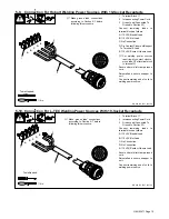
Page 23: ...ding power source Tools Needed 1 A B C D E 2 1 4 in 3 J L K V T C P D H G F E R S A M B N U Make ground lead connections according to Section 5 7 before following this procedure 5 10 Connection For L TEC Welding Power Sources With 19 Socket Receptacle Ref 802 310 Ref 193 749 1 Terminal Block 1T 2 Interconnecting Power Cord 3 Green Lead Connected To Ground In Section 5 7 Connect remaining leads to ...

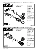
Page 24: ... B C D Make ground lead connections according to Section 5 7 before following this procedure 5 12 Connection For Lincoln Welding Power Sources With 14 Socket Receptacle Ref 802 310 Ref 193 749 1 Terminal Block 1T 2 Interconnecting Power Cord 3 Green Lead Connected To Ground In Section 5 7 Connect remaining leads to terminal block as follows A 115 VAC Neutral Lead B 115 VAC Hot Lead C No Connection...

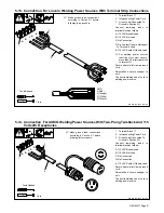
Page 25: ...ord to welding power source Tools Needed 1 A B C D E 2 1 4 in 3 32 Black 31 White GND 4 Orange 2 Red Make ground lead connections according to Section 5 7 before following this procedure 5 14 Connection For AIRCO Welding Power Sources With Two Prong Twistlock And 115 Volts AC Receptacles Ref 802 310 Ref 193 749 1 Terminal Block 1T 2 Interconnecting Power Cord 3 Green Lead Connected To Ground In Se...

Page 26: ...tions according to Section 5 7 before following this procedure 5 16 Connection For Miller Welding Power Sources With 14 Socket Receptacle Ref 802 310 Ref 193 749 1 Terminal Block 1T 2 Interconnecting Power Cord 3 White Lead 4 Black Lead 5 Red Lead 6 Green Lead Connected To Ground In Section 5 7 Connect remaining leads to terminal block as follows A White Lead 115 VAC Neutral B Black Lead 115 VAC H...

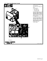
Page 27: ...te rubber cap before making adjustment Adjust potentiometer R73 using a small nonconductive screwdriver Rotate potentiometer clockwise to increase time it takes the motor to ramp up to speed 3 Burnback Potentiometer R42 Remove protective white rubber cap before making adjustment Adjust potentiometer R42 using a small nonconductive screwdriver Rotate potentiometer clockwise to increase burnback tim...

Page 28: ...n three seconds after an arc has been struck To end weld press and release gun trigger Power switch is on rear panel see Section 5 3 192 510 B 1 2 3 6 2 Optional Side Panel Controls Ref 802 310 B Ref 802 309 B 1 Optional Run In Speed Control The Run In Speed Control provides a means of selecting the rate at which welding wire will feed after preflow and before arc initiation After arc initiation t...

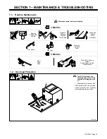
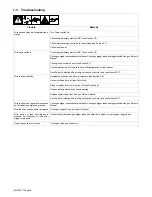
Page 29: ...Replace Cracked Weld Cable Gas Hose Gun Cable Replace Cracked Parts 6 Months Blow Out Or Vacuum Inside During Heavy Service Clean Monthly OR Clean Drive Rolls 7 2 Overload Protection Turn Off wire feeder and welding power source Stop engine on welding generat or 1 Supplementary Protector CB1 CB1 protects motor from overload Correct problem and manually reset supplementary protector 802 309 B 1 ...

Page 30: ...cally Readjust hub tension and drive roll pressure see Section 5 6 Use correct size drive roll see Parts List Clean or replace dirty or worn drive roll see Section 5 5 Remove weld spatter around nozzle opening Replace contact tip or liner See gun Owner s Manual Have Factory Authorized Service Agent check drive motor and control board PC1 Wire feeds when Jog switch is pressed but not when gun trigg...

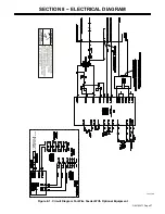
Page 31: ...OM 193471 Page 27 SECTION 8 ELECTRICAL DIAGRAM 193 378 C ROUTE WELD CABLE THROUGH REED SWITCH ASSEMBLY NOTE Figure 8 1 Circuit Diagram For Wire Feeder With Optional Equipment ...

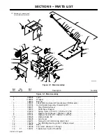
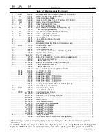
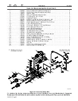
Page 32: ...487 Label Warning General Precautionary CE Domestic 1 4 072094 Hub Spindle Assembly Consisting Of 1 5 058427 Ring Retaining Spool 1 6 180572 Shaft Spool Support 1 7 010233 Spring Cprsn 970 Od X 120 Wire X 1 250 1 8 057971 Washer Flat Stl Keyed 1 500Dia X 125Thk 2 9 010191 Washer Fbr 656 Id X 1 500 Od X 125Thk 2 10 058628 Washer Brake Stl 2 11 058428 Hub Spool 1 12 248974 Tubing Stl 875 OD X12Ga Wa...

Page 33: ...4 Guide Wire Inlet 3 32 In Dia Consisting Of 1 36 082050 Liner Monocoil Inlet Wire 1 194265 Guide Wire Inlet 1 604612 Screw Set 8 32x 12 Cup Pt Sch Stl Pln 1 PLG4 115091 Housing Plug Skts 1 PLG3 115092 Housing Plug Skts 1 PLG6 131054 Housing Rcpt Skts 1 120304 Blank Snap In Nyl 250 Mtg Hole 4 107983 Blank Snap In Nyl 500 Mtg Hole 2 024103 Blank Snap In Nyl 750 Mtg Hole 2 000527 Blank Snap In Nyl 8...

Page 34: ... Ext 500 Shaft 1 15 192875 Insulator Motor Drive 4 Roll 1 16 187325 Insulator Drive Assembly 1 17 144172 Fitting Hose Brs Barbed M 3 16 Tbg X 250 20 1 18 238726 Housing Adapter Gun Feeder 1 19 124778 Knob T 2 000 Bar W 312 18 X 1 000lg 1 20 221654 Washer Shldr Insulating 2 21 079625 Washer Wave 500 Id X 750 Od X 015Thk 2 22 253187 Spacer Stl 500 Id X 875 Od X 14 Ga 1 23 092865 Key Stl 1 24 172077 ...

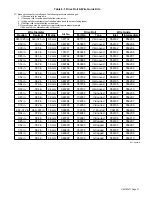
Page 35: ... No 087132 046780 046781 046782 046783 046784 044750 046785 046786 046787 046788 046792 046793 046794 046795 046796 083319 083320 046800 046801 Drive Roll Part No Type 087130 053695 053700 053697 053698 053699 072000 053701 053702 053706 053704 132958 132957 132956 132955 132960 083489 083490 053708 053710 V Grooved V Grooved V Grooved V Grooved V Grooved V Grooved U Grooved U Grooved U Grooved U ...

Page 36: ...OM 193471 Page 32 Notes ...

Page 37: ...Notes ...

Page 38: ...Notes Over 80 000 trained since 1930 400 Trade Square East Troy Ohio 45373 1 800 332 9448 www welding org Start Your Professional Welding Career Now ...

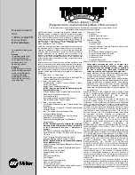
Page 39: ...uns and Subarc SAW Torches Remote Controls and RFCS RJ45 Replacement Parts No labor Roughneck Guns Spoolmate Spoolguns Miller s True Blue Limited Warranty shall not apply to 1 Consumable components such as contact tips cutting nozzles contactors brushes relays work station table tops and welding curtains or parts that fail due to normal wear Exception brushes and relays are covered on all engine d...

Page 40: ...h your personal records Always provide Model Name and Serial Style Number Contact a DISTRIBUTOR or SERVICE AGENCY near you Welding Supplies and Consumables Options and Accessories Personal Safety Equipment Service and Repair Replacement Parts Training Schools Videos Books Technical Manuals Servicing Information and Parts Circuit Diagrams Welding Process Handbooks Contact the Delivering Carrier to ...

Reviews: