background image

OM-253555 Page 28

Complete Parts List is available at www.MillerWelds.com

7-2.

Overload Protection

A complete Parts List is available at www.MillerWelds.com

OM-253555 Page 1

Ref. 251808-A

1

1

Supplementary Protector CB1

CB1 protects unit from overload. If CB1
opens, unit shuts down.

Reset supplementary protector.

7-3.

Wrapper Removal

A complete Parts List is available at www.MillerWelds.com

OM-253555 Page 1

Ref. 251808-A

Torx 25

Tools Needed:

1

2

OM-222 Page 1

allen_wrench

NGO’s

tools/

flathead

philips head

wrench

pliers

knife

heavy-duty workclamp

light-duty workclamp

wirecutter

frontcutter

allen_set

needlenose

steelbrush

nutdriver

chippinghammer

solderiron

stripcrimp

drill

torque wrench

socket wrench

hammer

awl

file

crimper

paintbrush

feelergauge

flashlight

ruler

toothbrush

greasegun

qtip (swab)

vicegrip

handream

punch

filterwrench

strapwrench

airgun

solvent

pinextractor

eprompuller

pipewrench

torque screwdriver

crescent wrench

Torx 25

Turn off power, and disconnect in-
put power plug from receptacle or
turn off and lockout/tagout line dis-
connect device before working on
unit.

Significant DC voltage can remain
on capacitors after unit is Off.
Check to see that front panel lights
(LEDs) have stopped flashing and
are off before removing wrapper.

1

Wrapper

2

Torx Screws (Fine Thread)

Remove Torx screws and slide wrapper off.

7-4.

Checking Shield Cup Shutdown System

A complete Parts List is available at www.MillerWelds.com

OM-253555 Page 1

Ref. 253 554-A

1

Always

turn

Off

power

when

changing or checking consum-
ables. Do not overtighten torch
shield cup. Gently finger-tighten
cup onto torch.

Power must be reset whenever the cup

shutdown system is activated.

1

Torch Shield Cup

Turn Power On and loosen shield cup. If
shutdown system works properly, Cup light
comes on. If not, immediately turn Off power
and have Factory Authorized Service Agent
check unit.

If system works properly, retighten cup and
reset power.

Summary of Contents for Spectrum 375 X-TREME

Page 1: ...L OM 253555G 2019 11 Processes Air Plasma Cutting and Gouging Description Air Plasma Cutter For product information Owner s Manual translations and more visit www MillerWelds com Spectrum 375 X TREME And XT 30 Torch ...

Page 2: ... service that meets the high standards of quality and value established in 1929 This Owner s Manual is designed to help you get the most out of your Miller products Please take time to read the Safety Precautions They will help you protect yourself against potential hazards on the worksite We ve made installation and operation quick and easy With Miller you can count on years of reliable service w...

Page 3: ...4 Unit Specifications 11 4 5 Torch Dimensions 14 4 6 Power Source Dimensions 14 4 7 Duty Cycle And Overheating 15 4 8 Environmental Specifications 15 SECTION 5 INSTALLATION 16 5 1 Selecting A Location 16 5 2 Connecting Gas Air Supply 16 5 3 Connecting And Disconnecting Work Cable 17 5 4 Connecting Work Clamp 17 5 5 Electrical Service Guide 18 5 6 Input Power Extension Cord Data 18 5 7 Generator Or...

Page 4: ......

Page 5: ...roperly prepared according to AWS F4 1 and AWS A6 0 see Safety Standards Connect work cable to the work as close to the cutting area as practical to prevent cutting current from traveling long possibly un known paths and causing electric shock sparks and fire hazards Do not use plasma cutter to thaw frozen pipes Never cut containers with potentially flammable materials inside they must be emptied ...

Page 6: ...etal Wear approved face shield or safety goggles with side shields Wear proper body protection to protect skin Wear flame resistant ear plugs or ear muffs to prevent sparks from entering ears NOISE can damage hearing Prolonged noise from some cutting applications can damage hearing if levels exceed limits speci fied by OSHA see Safety Standards Use approved ear plugs or ear muffs if noise level is...

Page 7: ...ual carefully before installing operating or servicing unit Read the safety information at the beginning of the manual and in each section Use only genuine replacement parts from the manufacturer Perform installation maintenance and service according to the Owner s Manuals industry standards and national state and lo cal codes FLYING METAL or DIRT can injure eyes Wear safety glasses with side shie...

Page 8: ...fpa org and www sparky org Safe Handling of Compressed Gases in Cylinders CGA Pamphlet P 1 from Compressed Gas Association Website www cganet com Safety in Welding Cutting and Allied Processes CSA Standard W117 2 from Canadian Standards Association Website www csagroup org Safe Practice For Occupational And Educational Eye And Face Pro tection ANSI Standard Z87 1 from American National Standards I...

Page 9: ...utre personne travaillant sur les lieux contre les étincelles et le métal chaud Assurez vous qu aucune étincelle ni particule de métal ne peut se glisser dans de petites fissures ou tomber dans d autres pièces Afin d éliminer tout risque de feu soyez vigilant et gardez toujours un extincteur à la portée de la main Si vous coupez sur un plafond un plancher ou une cloison soyez conscient que cela pe...

Page 10: ...sse doit être pincé correctement sur la pièce à couper métal contre métal et non de telle sorte qu il puisse se dé tacher ou sur la table de travail le plus près possible de la ligne de coupage Isoler la pince de masse quand pas mis à la pièce pour éviter le contact avec tout objet métallique DÉCHARGES ÉLECTRIQUES potentiellement mortelles Il reste une TENSION DC NON NÉGLIGEABLE dans les sources d...

Page 11: ...les nettoyer convenablement L ARC PLASMA peut provoquer des blessures La chaleur dégagée par le plasma d arc peut en traîner de sérieuses brûlures La force de l arc est un facteur qui s ajoute au danger de brûlures La chaleur intense et la puissance de l arc peuvent rapidement passer au travers de gants et de tissus N approchez pas le tube du chalumeau Ne saisissez pas la pièce à couper près de la...

Page 12: ...ter le cycle opératoire nominal Réduire l ampérage épaisseur avant de continuer à couper ou réduire le facteur de marche Danger D EXPLOSION D HYDROGÈNE Lors du coupage d aluminium sous l eau ou avec de l eau touchant le dessous de l aluminium une libération d hydrogène peut s accumuler sous la pièce Consultez votre ingénieur de coupage et les instructions de la ta ble de coupage L EXPLOSION DE LA ...

Page 13: ... Allied Processes CSA Standard W117 2 from Canadian Standards Association Website www csagroup org Safe Practice For Occupational And Educational Eye And Face Pro tection ANSI Standard Z87 1 from American National Standards In stitute Website www ansi org Standard for Fire Prevention During Welding Cutting and Other Hot Work NFPA Standard 51B from National Fire Protection Association Website www n...

Page 14: ...fe29 201 Disconnect input plug or power before working on machine Safe30 20 When power is applied failed parts can explode or cause other parts to explode 3 2 Miscellaneous Symbols And Definitions Amperage Voltage Protective Earch Ground GND PE On Off Rated No Load Volt age OCV Rated Supply Voltage Primary Voltage Conventional Load Voltage Rated Maximum Supply Current Rated Current Maximum Effecti...

Page 15: ...c circumstances The appropriate ness of all parameters and settings should be evaluated and modified by the end user as necessary based upon application specific require ments The end user is solely responsible for selection and coordination of appropriate equipment adoption or adjustment of default weld parameters and settings and ultimate quality and durability of all resultant welds Miller Elec...

Page 16: ...0 992 2 12 2 11 240 VAC 1 Phase 0 978 3 53 3 45 Peak kW at Arc Stretch 7 0 kW Output Rated Open Circuit Voltage U0 Type 400 Volts DC Electrode Negative Output Characteristic Constant Current Rated Output Current and Volt age I2 U2 at rated Input Volt age U1 Volts AC RMS U1 Amps DC I2 Volts DC U2 120 VAC 1 Phase 20 A 27 A 92 V 120 VAC 1 Phase 15 A 20 A 88 V 240 VAC 1 Phase 30 A 92 V Output Current ...

Page 17: ...ating Of Electrical Controls Trigger 30 VDC At 0 1 Amps Rating of Electrical Controls Cup 30 VDC At 1 Amp Approved Systems Spectrum 375 X TREME w XT30 torch Trigger Protection Safety Trigger Guard Safety Devices Safety Interlock Devices Shut Down Power Source Rated Capacity Edge Start 3 8 in At 18 ipm 457 mm min Sever Cut Capacity Edge Start 5 8 in Pierce Capacity 3 16 in Weight 2 2 lb 1 kg Travel...

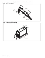
Page 18: ...arts List is available at www MillerWelds com 4 5 Torch Dimensions OM 253555 Page 5 Ref 253554 A 1 3 16 in 30 mm 8 3 4 in 222 mm 1 1 2 in 38 mm 4 6 Power Source Dimensions Ref 251808 A 13 1 8 in 333 mm 5 1 2 in 140 mm 9 in 229 mm ...

Page 19: ...t overheats thermostat s opens output stops Temperature trouble light goes On and cooling fan runs Wait fifteen minutes for unit to cool or temperature light to go off Re duce amperage or duty cycle before cutting or gouging NOTICE Exceeding duty cycle can dam age unit and void warranty 4 8 Environmental Specifications A IP Rating IP Rating IP23S This equipment is designed for outdoor use It may b...

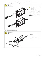
Page 20: ... NEC Ar ticle 511 or CEC Section 20 1 Shoulder Strap Use strap to lift unit 2 Line Disconnect Device Locate unit near correct input power supply 5 2 Connecting Gas Air Supply Ref 251808 A 3 1 2 ps head wrench crescent wrench 9 16 in Use only clean dry air with 90 to 120 psi 621 to 827 kPa pressure 1 Gas Air Inlet Opening 2 Hose From Gas Air Supply 3 Teflon Tape Obtain hose with 1 4 NPT right hand ...

Page 21: ...eptacle keyway and insert into receptacle Rotate plug clockwise hand tight only 1 4 turn to secure in receptacle To disconnect plug rotate counterclockwise until key aligns with keyway and pull plug from receptacle 5 4 Connecting Work Clamp A complete Parts List is available at www MillerWelds com 1 1 Connecting Work Clamp Ref 803640 A 1 2 1 Work Clamp 2 Workpiece Connect work clamp to a clean pai...

Page 22: ...ctrical Code NEC including article 630 1 If a circuit breaker is used in place of a fuse choose a circuit breaker with time current curves comparable to the recommended fuse 2 Time Delay fuses are UL class RK5 See UL 248 3 Normal Operating general purpose no intentional delay fuses are UL class K5 up to and including 60 amps and UL class H 65 amps and above 4 Maximum total length of copper input c...

Page 23: ...lect plug for power supply receptacle available at site Not all plugs shown are provided as standard with unit 2 Plug NEMA Type 5 15P 3 Receptacle NEMA Type 5 15R Cus tomer Supplied 4 Plug NEMA Type 5 20P Optional 5 Receptacle NEMA Type 5 20R Cus tomer Supplied 6 Plug NEMA Type 6 50P 7 Receptacle NEMA Type 6 50R Cus tomer Supplied Follow electrical service guide for 230 VAC Do not use plug rating ...

Page 24: ...t and check input volt age available at site The Auto Line circuitry in this unit auto matically links the power source to the primary voltage being applied either 120 or 240 VAC For 120 volts AC input power a 15 or 20 am pere individual branch circuit protected by time delay fuses or circuit breaker is required 1 Multi Voltage Plug And Power Cord Con nector NEMA Type 5 15P Plug Shown For multi vo...

Page 25: ...ry in this unit automatically adapts the power source to the primary voltage being applied either 120 or 240 VAC See rating label on unit and check input volt age available at site 1 Input Power Cord 2 Disconnect Device switch shown in the OFF position 3 Disconnect Device Grounding Terminal 4 Disconnect Device Line Terminals 5 Black And White Input Conductor L1 And L2 6 Green Or Green Yellow Groun...

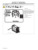
Page 26: ... the cutting out put and or the cut time or find more adequate power see Section NO TAG 2 Power Light 3 Trouble Lights See Section NO TAG 4 Power Switch Use switch to turn unit On or Off 253014 A Ref 251808 A 3 1 2 4 1 Output Control Use control to set cutting output If 22 27 amperes of cutting output is used with 120 VAC input power and the overload protection on the input power circuit fre quent...

Page 27: ... 115 2921 1 8 0 13 3 2 88 2235 3 16 0 19 4 8 50 1280 1 4 0 25 6 4 28 711 3 8 0 38 9 5 15 386 1 2 0 50 12 7 8 203 5 8 0 63 15 9 5 123 Recommended Cut Speed is approximately 80 of maximum Aluminum and Stainless Steel cut speeds at these thicknesses may be reduced as much as 20 Recommended Cut Speeds At 20 Amperes Output Mild Steel Material Thickness Recommended Cut Speeds In mm IPM mm min 16 ga 0 06...

Page 28: ...le and electrode Step 3 Maintain approximately a 90 angle to the workpiece surface for proper cutting results Step 4 Sparks should pass through the workpiece and out the bottom when cutting Step 5 If sparks flare back from surface this usually is an indication that either travel speed is too fast or amperage is set too low Step 6 When doing extended non shielded cutting maintain approximately 1 8 ...

Page 29: ...ielded cutting place drag shield on edge of metal For ex tended non shielded cutting use 1 8 in 3 2 mm standoff distance dragging tip will reduce tip life Step 3 Raise trigger lock and press trigger Pilot arc starts Step 4 After cutting arc starts slowly start moving torch across metal Step 5 Adjust torch speed so sparks go through metal and out bottom of cut Step 6 Pause briefly at end of cut bef...

Page 30: ... as possible Step 2 Hold torch at approximately 45 to the workpiece Raise trigger lock and press trigger Pilot arc starts Step 3 Rotate torch to upright position ap proximately 90 to surface When arc has pierced through workpiece start cutting Step 4 Maintain approximately 90 torch po sition to surface and continue cutting Step 5 Release trigger Postflow continues for approximately 20 seconds afte...

Page 31: ...place Reference Each Use Gas Air Pressure Torch Tip Electrode And Shield Cup Sections 5 2 and 7 6 Every Week Shield Cup Shutdown System Section 7 4 Every 3 Months Damaged Or Unread able Labels Air Filter Regulator OM 279640 Page 32 Every 8 Hours Spills Oil Level Worn or Damaged Air Oil Hoses Cooling System Cracked Parts Gas Air Hose Sections 7 5 and 9 Torch Body Cable Every 6 Months Inside Unit To...

Page 32: ...nnect device before working on unit Significant DC voltage can remain on capacitors after unit is Off Check to see that front panel lights LEDs have stopped flashing and are off before removing wrapper 1 Wrapper 2 Torx Screws Fine Thread Remove Torx screws and slide wrapper off 7 4 Checking Shield Cup Shutdown System A complete Parts List is available at www MillerWelds com Ref 253 554 A 1 Always ...

Page 33: ...andream filterwrench crescent wrench Torx 25 Significant DC voltage can remain on capacitors after unit is Off Check to see that front panel lights LEDs have stopped flashing and are off before removing wrapper Turn power Off and disconnect input power plug from receptacle Remove wrapper from unit see Section 7 3 1 Filter Base 2 Filter 3 Filter Cup Unscrew filter cup from base Remove cup Unscrew f...

Page 34: ...lace Be sure to use genuine re placement parts from the manufacturer A good practice is to replace both the tip and electrode at the same time 1 Shield Cup Remove shield cup Check cup for cracks and replace if necessary 2 Tip 3 Opening Remove tip Check tip and replace if open ing is deformed or 50 oversize If inside of tip is not clean and bright clean with steel wool Be sure to remove any pieces ...

Page 35: ...is between 90 to 120 psi 621 to 827 kPa Cup On Torch cup is loose or off Once cup is tight ened unit power must be cycled off and back on again Cup Flashing rate is steady for 15 seconds or until torch trigger is pressed again whichever comes first No arc was established Check consumables or torch Cup Repetitive flashing rate of two quick cycles then a one second pause for a 15 second pe riod or u...

Page 36: ...has cooled Have Factory Authorized Service Agent check control board Status lights not working Have Factory Authorized Service Agent check unit Power light flashing status lights off Reset power switch If problem continues have qualified technician check input line power Pressure status light flashes Unit lost pressure momentarily while cutting Check air line for leaks Cup status light flashes Uni...

Page 37: ...OM 253555 Page 33 ...

Page 38: ...OM 253555 Page 34 SECTION 8 ELECTRICAL DIAGRAMS Figure 8 1 Circuit Diagram ...

Page 39: ...OM 253555 Page 35 286338 A ...

Page 40: ...r 1 5 249949 XT30 12FT Hand Held Replacement 1 6 263799 Cable Work 12 ft 12 ga w 200A Clamp Plug 1 7 253524 Label XT30 Consumables 1 8 219259 Adapter Power Cable 5 20P 115v 20A 1 Ref 253524 A 1 2 3 4 5 7 6 Figure 9 1 Consumable Parts For XT30 Torch Consumable Parts For XT30 Torch Item No Dia Mkgs Part No Description Quantity 1 249930 Drag Shield 2 249932 Retaining Cup 3 249927 Tip 4 249931 Swirl R...

Page 41: ...ia Mkgs Part No Description Quantity 1 259870 Torch Handle Kit XT30 1 2 249971 Torch Trigger 1 3 249957 Leads 12 ft XT30 1 4 252938 Torch Body Kit 1 5 249972 Torch Trigger Assembly w Spring 1 6 249973 Cup Detect Switch w Screws 30 60 Amp 1 252951 Grease Silicone 1 249949 Torch Replacement 12 ft XT30 1 ...

Page 42: ...Notes ...

Page 43: ...r SAR Boxes and Panels TIG Torches No Labor Tregaskiss Guns No Labor Water Cooling Systems Wireless Remote Foot Hand Controls and Receivers Work Stations Weld Tables No Labor 5 6 Months Parts Batteries 6 90 Days Parts Accessories Kits ArcReach Heater Quick Wrap and Air Cooled Cables Canvas Covers Induction Heating Coils and Blankets Cables and Non Electronic Controls MDX Series MIG Guns M Guns MIG...

Page 44: ...istributor Address City State Zip Register your product at www MillerWelds com Register For Service Contact a DISTRIBUTOR or SERVICE AGENCY near you Always provide Model Name and Serial Style Number Contact your Distributor for Welding Supplies and Consumables Options and Accessories Personal Protective Equipment PPE Service and Repair Replacement Parts Training Schools Videos Books Welding Proces...

Reviews: