background image

.

A complete Parts List is available at www.MillerWelds.com

OM-264 267 Page 32

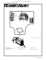
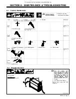
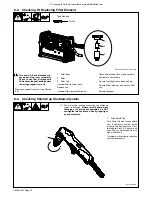
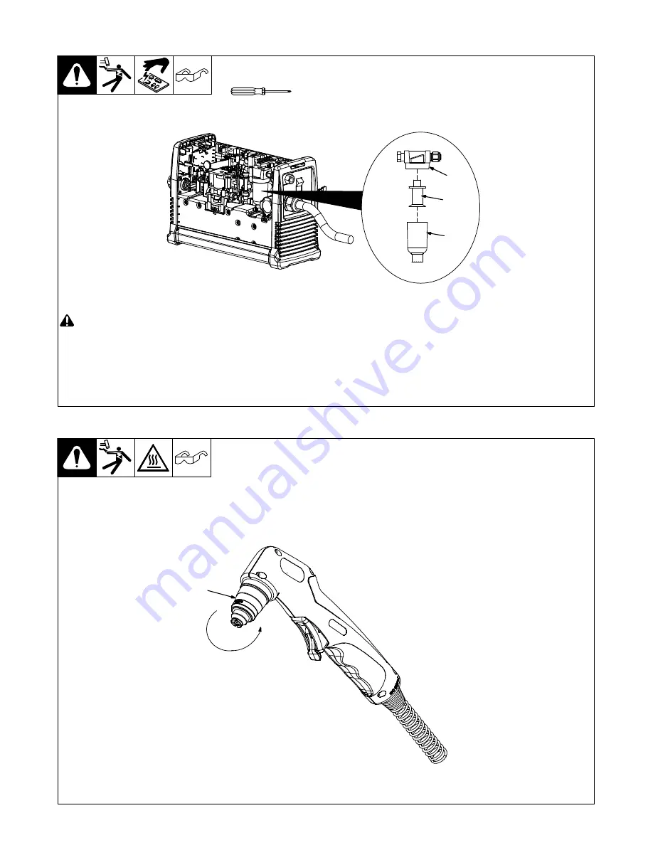
8-3. Checking Or Replacing Filter Element

!

Turn power Off, and disconnect in-

put power plug from receptacle.

Check to see that all diagnostic

LEDs have stopped flashing before

removing wrapper from unit.

Remove wrapper from unit (see Section

8-2).

1

Filter Base

2

Filter

3

Filter Cup

Unscrew filter cup from base.
Remove cup.
Unscrew filter element from base.

Check filter element for dirt and moisture,

and replace if necessary.

Be sure that all parts are clean and dry.

Reinstall filter element, and secure filter

cup.

Reinstall wrapper.

Ref. 805 327-A / Ref. 264 954-B

Torx 25

Tools Needed:

1

2

3

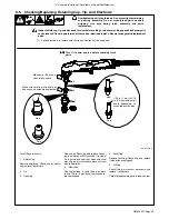
8-4. Checking Shield Cup Shutdown System

Ref. 253 554-A

1

Torch Shield Cup

Turn Power On and loosen shield

cup. If shutdown system works

properly, Cup light comes on. If not,

immediately turn Off power and

have Factory Authorized Service

Agent check unit.
If system works properly, retighten

cup and reset power.

1

.

Power must be reset whenever the cup shutdown
system is activated. 

Always turn Off power when

changing or checking consumables. Do NOT

overtighten torch shield cup. Gently finger tight-

en cup onto torch.

Summary of Contents for XT40 Torch

Page 1: ...Processes Description Air Plasma Cutting and Gouging Air Plasma Cutter OM 264 267C 2014 09 Spectrum 625 X TREME And XT40 Torch R File Plasma Cutters Visit our website at www MillerWelds com...

Page 2: ...ntinue the tradition They re just as committed to providing equipment and service that meets the high standards of quality and value established in 1929 This Owner s Manual is designed to help you get...

Page 3: ...cifications 11 4 3 Torch Dimensions And Weight 12 4 4 Duty Cycle And Overheating 13 4 5 Power Source Dimensions And Weight 13 4 6 Environmental Specifications 13 SECTION 5 INSTALLATION 14 5 1 Selectin...

Page 4: ...hield Cup Shutdown System 32 8 5 Checking Replacing Retaining Cup Tip And Electrode 33 8 6 Status Trouble Lights 34 8 7 Troubleshooting Power Source 35 8 8 Troubleshooting Torch 35 SECTION 9 ELECTRICA...

Page 5: ...vy cotton wool Body protection includes oil free clothing such as leather gloves heavy shirt cuffless trousers high shoes and a cap D Do not locate unit on or over combustible surfaces D Remove any co...

Page 6: ...r s instructions for adhesives coatings cleaners consumables coolants degreasers fluxes and metals D Work in a confined space only if it is well ventilated or while wearing an air supplied respirator...

Page 7: ...pose FALLING EQUIPMENT can injure D Use lifting eye to lift unit only NOT running gear gas cylinders or any other accessories D Use equipment of adequate capacity to lift unit D If using lift forks to...

Page 8: ...b site www ansi org Standard for Fire Prevention During Welding Cutting and Other Hot Work NFPA Standard 51B from National Fire Protection Association Quincy MA 02269 phone 1 800 344 3555 website www...

Page 9: ...onscient que cela peut entra ner un feu de l autre c t D Ne pas effectuer le soudage sur des conteneurs ferm s tels que des r servoirs tambours ou conduites moins qu ils n aient t pr par s correctemen...

Page 10: ...se sous tension toute pi ce d fectueuse des sources d alimentation de l inverseur peut exploser ou faire exploser d autres pi ces Pour entretenir les inverseurs toujours porter un masque protecteur et...

Page 11: ...branchez le cordon d alimentationavant de d monter le chalumeau ou de changer une pi ce du chalumeau D Utilisez uniquement le ou les chalumeaux recommand s dans le manuel de l op rateur Les bouteille...

Page 12: ...r l quipement c bles et cordons distance des v hicules mobiles lors de toute op ration en hauteur D Suivre les consignes du Manuel des applications pour l quation de levage NIOSH r vis e Publication N...

Page 13: ...andard for Fire Prevention During Welding Cutting and Other Hot Work NFPA Standard 51B from National Fire Protection Association Quincy MA 02269 phone 1 800 344 3555 website www nfpa org OSHA Occupati...

Page 14: ...C Adjust Air Gas Pressure Low Air Pressure Light V Volts Increase No Do Not Do This Temperature Protective Earth Ground Single Phase Constant Current Voltage Input On Off Percent Direct Current U0 Rat...

Page 15: ...ff 120 VAC 1 Phase 20 A 25 1 11 2 120 VAC 1 Phase 15 A 18 1 10 7 240 VAC 1 Phase 26 7 18 9 Power Factor kVA kW at Rated Output Volts AC RMS U1 Power Factor kVA kW 120 VAC 1 Phase 20 A 0 969 3 02 2 93...

Page 16: ...f Electrical Controls Cup 30 VDC at 1 Amp Approved Systems Spectrum 625 X TREME w XT40 torch Trigger Protection Safety trigger guard Safety Devices Safety interlock devices shut down power source Rate...

Page 17: ...ranty Overheating sduty1 5 95 Ref 264 954 B 5 Minutes Cutting 5 Minutes Resting 50 duty cycle 2 Minutes Cutting 8 Minutes Resting 3 1 2 Minutes Cutting 6 1 2 Minutes Resting 35 duty cycle 0 15 Minutes...

Page 18: ...allation may be required where gasoline or volatile liquids are present see NEC Article 511 or CEC Section 20 Location 1 18 in 460 mm 18 in 460 mm Do not move or operate unit where it could tip 5 2 Co...

Page 19: ...position To disconnect torch Rotate collar to release torch connector from receptacle and pull torch connector away from unit Ref 264 954 B 2 1 3 5 4 Connecting And Disconnecting Work Cable Ref 264 9...

Page 20: ...ircuit breaker is required See Section 4 2 27 Max Recommended Standard Fuse Rating In Amperes 1 Time Delay Fuses 2 35 Normal Operating Fuses 3 45 Min Input Conductor Size In AWG 4 10 Max Recommended I...

Page 21: ...r NEMA Type 6 50P 7 Receptacle NEMA Type 6 50R Customer Supplied 8 Receptacle NEMA Type L6 30R Customer Supplied Follow electrical service guide for 240 VAC in Section 5 6 Do not use plug rating to si...

Page 22: ...Article 511 or CEC Sec tion 20 See rating label on unit and check input voltage available at site The Auto Line circuitry in this unit automatically links the power source to the primary voltage being...

Page 23: ...A complete Parts List is available at www MillerWelds com OM 264 267 Page 19 Notes...

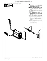
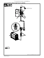
Page 24: ...vailable at www MillerWelds com OM 264 267 Page 20 5 10 Connecting 1 Phase Input Power For 240 VAC Input10 2014 09 803 766 B Ref 254 665 A Ref 251 808 A 2 1 L1 L2 1 GND PE Earth Ground 6 5 3 4 7 Tools...

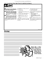
Page 25: ...Device switch shown in the OFF position 3 Disconnect Device Grounding Terminal 4 Disconnect Device Line Terminals 5 Black And White Input Conductor L1 And L2 6 Green Or Green Yellow Grounding Conduct...

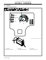
Page 26: ...ndard Front Panel Controls 1 Output Control Use control to set cutting output 2 Power Light 3 Trouble Lights See Section 8 6 4 Power Switch Use switch to turn unit On or Off Ref 253 015 A Ref 264 954...

Page 27: ...Output Control Use control to set cutting output 2 Power Light 3 Trouble Lights See Section 8 6 4 Automation Receptacle 5 Power Switch Use switch to turn unit On or Off Ref 253 015 A Ref 264 954 B Ref...

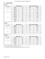
Page 28: ...2 0 50 12 70 22 559 5 8 0 63 15 88 13 330 Stainless Arc Current Material Thickness Recommended Cut Speeds Inches mm IPM mm min 30 16ga 0 06 1 52 174 4 419 12ga 0 11 2 67 86 2 184 40 12ga 0 11 2 67 154...

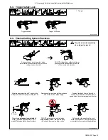
Page 29: ...ults Always connect work clamp to a clean paint free location on workpiece as close to cutting area as possible 90 DO NOT start pilot arc without cutting or gouging as this shortens the service life o...

Page 30: ...nd press trigger Pilot arc starts Postflow continues for approx 20 seconds after releasing trigger cutting arc can be instantly restarted during postflow by raising trigger lock and pressing trigger T...

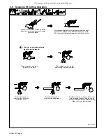
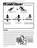
Page 31: ...4 8 mm Start gouging across workpiece surface Maintain approximately a 45 angle to surface Release trigger Postflow continues for approx 20 seconds after releasing trigger arc can be instantly restart...

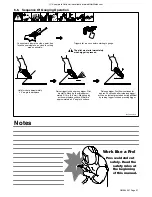
Page 32: ...by raising trigger lock and pressing trigger The pilot arc starts immediately when trigger is pressed Hold torch at approximately 45 to the workpiece Raise trigger lock and press trigger Pilot arc sta...

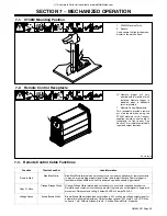
Page 33: ...nctions Function Twisted Lead Set Lead Information Remote Start Blue Blue White Blue Blue White twisted lead set connects to a customer supplied set of remote contacts to provide a remote trigger inpu...

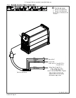
Page 34: ...Connect plug to receptacle on unit front panel 1 Remote Control Cable Remote Start Blue Blue White Orange Orange White Relay Contacts 3 amps 28 VDC or Okay To Move 2 3 amps 120 VAC Brown Brown White...

Page 35: ...Tip Electrode And Shield Cup Every Week Section 8 4 n Shield Cup Shutdown System Every 3 Months Section 8 3 10 l Damaged Or Unreadable Labels Air Filter Regulator l Cracked Parts n l Gas Air Hose n l...

Page 36: ...if necessary Be sure that all parts are clean and dry Reinstall filter element and secure filter cup Reinstall wrapper Ref 805 327 A Ref 264 954 B Torx 25 Tools Needed 1 2 3 8 4 Checking Shield Cup S...

Page 37: ...Remove shield cup Check cup for cracks and replace if necessary 2 Tip 3 Opening Remove tip Check tip and replace if open ing is deformed or 50 oversize If inside of tip is not clean and bright clean...

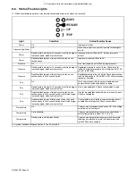
Page 38: ...input pressure to unit is between 90 to 120 psi 621 to 827 kPa or pressure transducer has failed Cup On Torch cup is loose or off Once cup is tightened unit power must be cycled off and back on again...

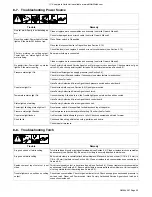
Page 39: ...run the Trouble light goes out when the unit has cooled Have Factory Authorized Service Agent check control board Status lights not working Have Factory Authorized Service Agent check unit Power light...

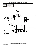
Page 40: ...OM 264 267 Page 36 SECTION 9 ELECTRICAL DIAGRAM Figure 9 1 Circuit Diagram For Spectrum 625 X TREME...

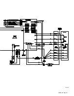
Page 41: ...OM 264 267 Page 37 264 143 A...

Page 42: ...OM 264 267 Page 38 Figure 9 2 Circuit Diagram For Spectrum 625 X TREME CNC...

Page 43: ...OM 264 267 Page 39 265 480 A...

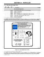
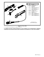
Page 44: ...bel XT40 Consumables 1 254331 Adapter 5 20PXL630R 1 A complete Parts List is available on line at www MillerWelds com To maintain the factory original performance of your equipment use only Manufactur...

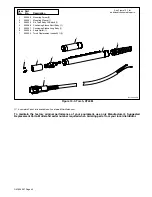
Page 45: ...260 633 XT40 12ft Hand Held Torch w Disconnect Replacement 1 260 635 XT40 20ft Hand Held Torch w Disconnect Replacement 1 See Figure 10 1 for additional consumable parts 1 1 2 3 4 5 Item No Part No D...

Page 46: ...330 Torch Replacement Leads 25 ft 1 Part No Item No Description 4 See Figure 10 1 for additional consumable parts 3 2 1 Ref 264 954 A 5 7 6 Figure 10 3 Torch XT40M A complete Parts List is available o...

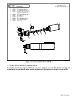
Page 47: ...8 249 926 30 40 Amp Electrode 1 9 249 969 O Ring 1 Part No Item No Description See Figure 10 1 for additional consumable parts Ref 264 954 A 1 2 3 4 5 6 7 8 9 Figure 10 4 Consumable Parts For XT40M A...

Page 48: ...Notes...

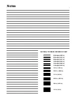
Page 49: ...auge 063 in 22 Gauge 031 in 24 Gauge 025 in 20 Gauge 037 in 18 Gauge 050 in 14 Gauge 078 in 1 8 in 125 in 3 16 in 188 in 1 4 in 25 in 5 16 in 313 in 3 8 in 375 in 1 2 in 5 in MATERIAL THICKNESS REFERE...

Page 50: ...Notes Work like a Pro Pros weld and cut safely Read the safety rules at the beginning of this manual...

Page 51: ...er s True Blue Limited Warranty shall not apply to 1 Consumable components such as contact tips cutting nozzles contactors brushes relays work station table tops and welding curtains or parts that fai...

Page 52: ...your personal records Always provide Model Name and Serial Style Number Contact a DISTRIBUTOR or SERVICE AGENCY near you Welding Supplies and Consumables Options and Accessories Personal Safety Equip...

Reviews: