PL-565
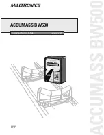
Accumass BW500
Page 3
Table of Contents
About this….................................................................................................................7
About This Manual ...........................................................................................7
About the Accumass BW500 ...........................................................................8
Accumass BW500 features: ......................................................................8
Specifications..............................................................................................................9
Installation .................................................................................................................13
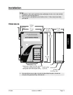
Dimensions ....................................................................................................13
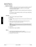
Optional Plug-ins............................................................................................14
SmartLinx
®
Module ..................................................................................14
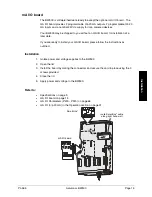
mA I/O board ...........................................................................................15
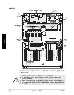
Layout ............................................................................................................16
Interconnection ..............................................................................................17
System Diagram ......................................................................................17
Scale – One Load Cell ............................................................................18
Scale – Two Load Cell ............................................................................19
Scale – Four Load Cell............................................................................20
Scale – LVDT ..........................................................................................21
Speed.............................................................................................................22
Constant Speed (No Sensor) ..................................................................22
Speed Sensor..........................................................................................22
Auxiliary Inputs...............................................................................................23
Auto Zero .......................................................................................................23
RS-232 Port 1 ................................................................................................23
Printers ....................................................................................................23
Computers and Modems .........................................................................24
Remote Totalizer............................................................................................24
mA Output 1...................................................................................................24
Relay Output ..................................................................................................25
RS-485 Port 2 ................................................................................................25
Daisy Chain .............................................................................................25
Terminal Device ......................................................................................25
RS-232 Port 3 ................................................................................................26
Power Connections........................................................................................26
mA I/O Board .................................................................................................27
Installing/Replacing the Memory Back-up Battery.........................................27
Start Up ......................................................................................................................29
Orientation .....................................................................................................29
Display and Keypad ................................................................................29
Program Mode ...............................................................................................30
General....................................................................................................30
Run Mode ................................................................................................31
Initial Start Up ................................................................................................32
Power Up.................................................................................................32
Programming ...........................................................................................32
Load Cell Balancing .......................................................................................35
Typical two load cell belt scale ................................................................35
Zero Calibration .......................................................................................38
Span Calibration ......................................................................................39
Run Mode ................................................................................................40
Summary of Contents for ACCUMASS BW500
Page 1: ...ACCUMASS BW500 Instruction Manual PL 565 January 2001 CCUMASS BW500 33455650 Rev 1 2...
Page 6: ...Page 6 Accumass BW500 PL 565...
Page 12: ...Page 12 Accumass BW500 PL 565 Specifications...
Page 28: ...Page 28 Accumass BW500 PL 565 Installation...
Page 88: ...Page 88 Accumass BW500 PL 565 Parameters...
Page 94: ...Page 94 Accumass BW500 PL 565 Operation...
Page 106: ...Page 106 Accumass BW500 PL 565 PID Control...
Page 110: ...Page 110 Accumass BW500 PL 565 Batching...
Page 112: ...Page 112 Accumass BW500 PL 565 Certification...

