


7ML19981CX01
ILE-61 Sensing Head – INSTRUCTION MANUAL
Page 11
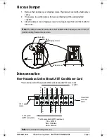
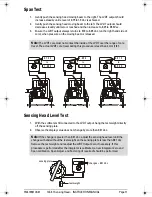
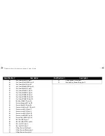
Span Test
1.
Gently push the sensing head moving beam to the right. The LVDT output should
increase steadily until a level of 0.75 to 1.0 Vac is achieved.
2.
Gently push the sensing head moving beam to the left. The LVDT output should
decrease steadily until zero is reached and then increase to 0.25 to 0.50 Vac.
3.
Ensure the LVDT output always returns to 0.10 to 0.05 Vac, (on the right hand side of
zero), when pressure on the moving beam is released.
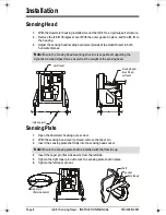
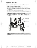
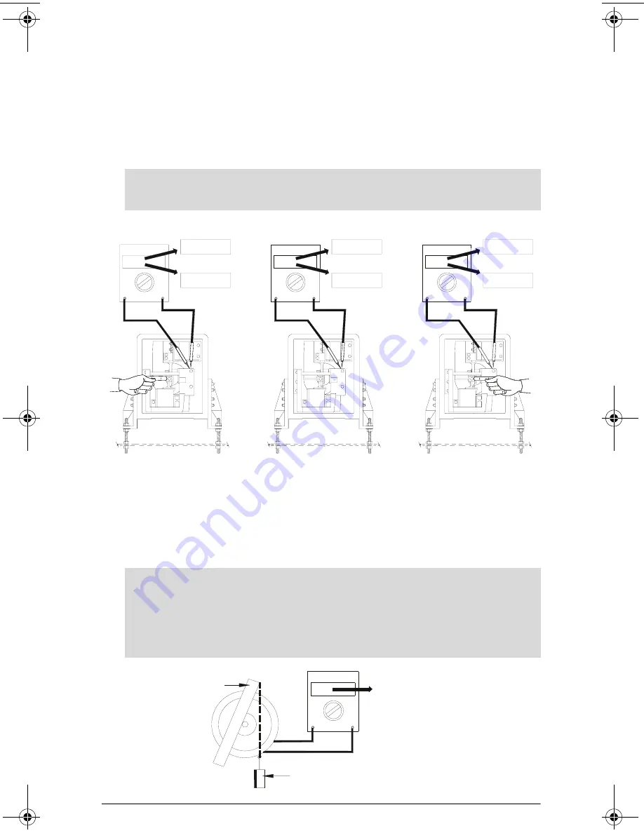
Sensing Head Level Test
1.
With the voltmeter still connected to the LVDT output, hang the test weight directly
off the sensing plate.
2.
Observe the display value does not change by more than 0.01 Vac.
Note:
The LVDT core must not contact the inside of the LVDT over the range of core
travel. The actual LVDT core travel during this procedure is less than 3 mm (1/8").
0 . 7 5 0
1 . 0 0 0
0 . 1 5 0
0 . 0 5 0
0 . 0 1 5
0 . 5 0 0
to
to
to
Note:
If the change is greater than 0.01 Vac, adjust the sensing head level until the
change with and without the test weight on the sensing plate is less than 0.01 Vac.
Remove the test weight and readjust the LVDT Output Zero, if necessary. If this
procedure is performed after the integrator is calibrated, a new integrator Zero and
Span calibration, Span Adjust, and Factoring (if required) should be performed.
changes < 0.01 Vac
test weight
sensing plate
376draft1.fm Page 11 Wednesday, November 21, 2001 1:54 PM
Siemens Industrial
Summary of Contents for ILE-61
Page 1: ...ILE 61 SENSING HEAD November 2001 LE 61 SEINSIING HEA Instruction Manual PL 376...
Page 24: ......
Page 25: ...Notes...
Page 26: ...Notes...
Page 27: ......
Page 28: ...7ML19981CX01...


