


Page 14
ILE-61 Sensing Head – INSTRUCTION MANUAL
7ML19981CX01
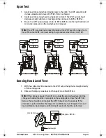
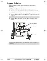
8.
Draw the main assembly away from the main frame.
9.
Remove the outer retaining ring and inner gasket, (8 bolts).
10. Install the new inner gasket and reverse the procedure (steps 1 through 9).
11. Perform the LVDT output zero procedure.
12. Referring to the integrator instruction manual, perform an integrator Zero and Span
calibration. Perform a Span Adjust if calibration accuracy appears affected.
Note:
The main assembly is heavy and awkward to handle; ensure it is
supported well.
376draft1.fm Page 14 Wednesday, November 21, 2001 1:54 PM
Summary of Contents for ILE-61
Page 1: ...ILE 61 SENSING HEAD November 2001 LE 61 SEINSIING HEA Instruction Manual PL 376...
Page 24: ......
Page 25: ...Notes...
Page 26: ...Notes...
Page 27: ......
Page 28: ...7ML19981CX01...


