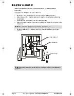

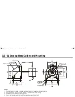


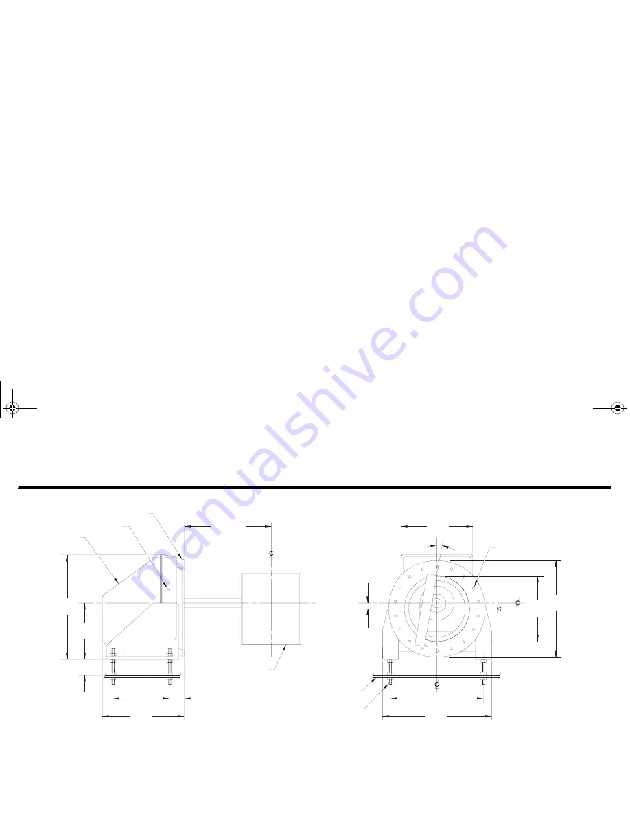
ILE - 61 Sensing Head Outline and Mounting
Notes:
1.
Refer to Flowmeter drawing for sensing head mounting hole to flowguide centre line dimension.
2.
Sensing head support plate should be rigid and independent of flowmeter housing.
3.
All dimensions in millimeters: ( ) denotes inches.
4.
Ensure that the outer gasket seal to the Flowmeter housing wall is dust tight.
outer gasket
conduit entry
½” NPT internal
fibreglass cover
560
(22.05)
318
(12.52)
60
(2.36)
300
(11.81)
420
(16.54)
sensing
plate
see note 1
support plate
(by customer)
16 (0.63) dia.
(4 levelling rods)
560
(22.05)
500
(19.64)
490
(19.29)
340
(13.34)
380
(14.96)
as req’d
8 (0.31 dia. 18 bolts
on 460 (18.11) BCD.
(22.44)
outer
gasket
sensing head
376draft1.fm Page 18 Wednesday, November 21, 2001 1:54 PM
Summary of Contents for ILE-61
Page 1: ...ILE 61 SENSING HEAD November 2001 LE 61 SEINSIING HEA Instruction Manual PL 376...
Page 24: ......
Page 25: ...Notes...
Page 26: ...Notes...
Page 27: ......
Page 28: ...7ML19981CX01...


