background image

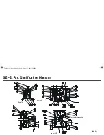
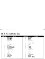
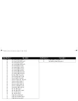
ILE - 61 Part Identification Table

Identification # 

Description 

ILE-61 body (cast frame)

Mounting Bracket (RH.)

Mounting Bracket (LH.)

4 Dynamic 

Beam 

(moving)

Static Beam (RH.)

Static Beam (LH.)

7 Damper 

Cylinder

Top Inner Leaf Spring Bracket

Top Outer Leaf Spring Bracket

10 

Leaf Spring, qty 4

11 

Bottom Inner Leaf Spring Bracket

12 

Bottom Outer Leaf Spring Bracket

13 

Outer Gasket Outer Ring

14 

Outer Gasket Inner Ring

15

Outer Gasket (silicon or neoprene)

16

Inner Gasket Outer Retainer

17 

Inner Gasket Inner Retainer

18 Inner 

Gasket

19

Calibration Arm

20 Calibration 

Pulley

21 

Calibration Pulley Shaft

22 

String Fixing Bolt

23 Damper 

Cover

24 Damper 

Cover 

Spring

25 Damper 

Window

26

Damper Shaft

27

Damper Piston

28

Damper Piston Shaft

29

Damper Fill Cap

30

Static Beam Stiffening Rod

31

Outer Leaf Spacer (qty 16)

32

Inner Leaf Spacer (qty 8)

33

Taper Pin

34

LVDT

35

LVDT Spring

36

LVDT Retainer

37

LVDT Transformer

38

Terminal Block (or 38A)

38A

LVDT Conditioner Card

39

Nameplate

40

Fibreglass Cover

41

Cover Gasket

42

LVDT Core

43

LVDT Calibrating Flange

44

Range Spring

45

Range Spring Retainer (RH.)

46

Range Spring Retainer (LH.)

47

Cap Screw M3x20, SS, (qty 2)

Identification # 

Description 

376draft1.fm  Page 20  Wednesday, November 21, 2001  1:54 PM

Summary of Contents for ILE-61

Page 1: ...ILE 61 SENSING HEAD November 2001 LE 61 SEINSIING HEA Instruction Manual PL 376...

Page 2: ...n and in electronic version We encourage users to purchase authorized bound manuals or to view electronic versions as designed and authored by Siemens Milltronics Process Instruments Inc Siemens Millt...

Page 3: ...rdous Unit with Remote Located LVDT Conditioner Card 9 Calibration 10 General 10 LVDT Output 10 Zero Adjustment 10 Span Test 11 Sensing Head Level Test 11 Integrator Calibration 12 Maintenance and Spa...

Page 4: ...nsing plate The horizontal impact force of the material deflecting the sensing plate displaces the core of the sensing head LVDT linear variable differential transformer The LVDT output signal is prop...

Page 5: ...TPH max Product fine powder to 25 mm 1 Product Temperature 40 to 232 C 40 to 450 F Ambient Temperature 40 to 60 C 40 to 140 F Accuracy 1 of full scale Repeatability 0 2 Classification CSA certified ge...

Page 6: ...ow Corning 200 Options Epoxy Teflon1 or Tufram2 frame coating Epoxy painted mild steel or stainless steel rear cover CSA Class I groups C D Class 2 groups E F G Approvals CE SENSING PLATE Construction...

Page 7: ...rovals CE Enclosure NEMA 4 remote mounted unit Cable For connection between LVDT Conditioner Card and Integrator Belden 8404 4 conductor shielded 20 AWG or equivalent 150 m 500 ft maximum Belden 9260...

Page 8: ...2 With the sensing head cover removed remove the taper pin 3 Insert the sensing plate shaft fully into the sensing head socket 4 Insert the taper pin flat side down from the left side 5 Tighten the r...

Page 9: ...use Interconnection Non Hazardous Unit without LVDT Conditioner Card See note below for Encapsulated Hazardous rated LVDT color codes Note The damper must be full and free of air bubbles with the damp...

Page 10: ...from SF500 terminal 13 to conditioner terminal block marked Integrator EXC For further connection information on specific LVDTs consult Milltronics 11 14 1 2 11 1 6 12 2 7 13 3 8 14 15 16 17 4 9 5 10...

Page 11: ...pecific LVDTs consult Milltronics 11 14 1 2 11 1 6 12 2 7 13 3 8 14 15 16 17 4 9 5 10 18 V S S V SHLD LOAD CELL EXCITATION LCA LCA LCB LCB SHLD LCC SIG LCC COM LCD CNST LCD SHLD LOAD CELL INPUTS E X C...

Page 12: ...ate in TPH 1TPH Use 60 grams for A 300 flowmeters e g If the Test Weight used with an E 300 flowmeter is 7000 grams Test Rate 7000 grams 155 TPH 45 grams TPH LVDT Output Zero Adjustment 1 Connect a vo...

Page 13: ...hang the test weight directly off the sensing plate 2 Observe the display value does not change by more than 0 01 Vac Note The LVDT core must not contact the inside of the LVDT over the range of core...

Page 14: ...monofilament fishing line or fine flexible cable to the Test Weight 3 Route the other end of string over the calibration pulley 4 Attach the free end of the string to the string fixing bolt Ensure th...

Page 15: ...rforming the following procedure 1 Remove the ILE 61 fibreglass cover 10 bolts 2 Bolt down the viscous damper cover to the shipping position 2 bolts 3 Remove the sensing plate from the sensing head 4...

Page 16: ...lts 10 Install the new inner gasket and reverse the procedure steps 1 through 9 11 Perform the LVDT output zero procedure 12 Referring to the integrator instruction manual perform an integrator Zero a...

Page 17: ...Moving the range spring to a location further away from the pivot point leaf spring increases the maximum flowrate capacity Range Spring Removal 1 Observe the range spring mounting position 3 positio...

Page 18: ...tion Integrator not prepared for operation Refer to Fig 4 Integrator LVDT Interconnection Refer to Installation Viscous Damper Program and Calibrate the integrator Span adjustment does not have enough...

Page 19: ...es not touch the damper cylinder wall at any flow rate the LVDT core does not touch the inside of the LVDT at any flow rate the viscous damper fluid is free of large air bubbles and the fluid level is...

Page 20: ...tes inches 4 Ensure that the outer gasket seal to the Flowmeter housing wall is dust tight outer gasket conduit entry NPT internal fibreglass cover 560 22 05 318 12 52 60 2 36 300 11 81 420 16 54 sens...

Page 21: ...0 39 22 34 37 35 66 36 49 38 47 19 56 65 41 53 64 40 56 54 4 78 49 63 5 20 21 76 13 15 16 64 58 60 68 14 60 52 50 17 18 54 42 43 48 62 67 56 65 6 11 12 3 56 65 1 77 57 65 2 7 44 45 46 49 53 65 55 FIG...

Page 22: ...Inner Gasket 19 Calibration Arm 20 Calibration Pulley 21 Calibration Pulley Shaft 22 String Fixing Bolt 23 Damper Cover 24 Damper Cover Spring 25 Damper Window 26 Damper Shaft 27 Damper Piston 28 Damp...

Page 23: ...r Flat M8 SS qty 30 61 Washer Lock 6 1mm I D SS qty 2 62 Washer Lock M4 SS qty 3 63 Washer Lock M5 SS qty 8 64 Washer Lock M8 SS qty 32 65 Washer Lock M10 SS qty 52 66 Washer Plate M5 SS qty 10 67 Nut...

Page 24: ......

Page 25: ...Notes...

Page 26: ...Notes...

Page 27: ......

Page 28: ...7ML19981CX01...

Reviews: