
Page 6
ILE-61 Sensing Head – INSTRUCTION MANUAL
7ML19981CX01
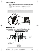
Installation
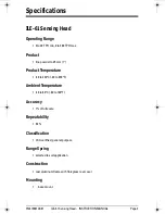
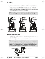
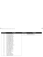
Sensing Head
1.
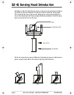
With the flowmeter housing installed, mount the ILE-61 to a rigid support structure.
2.
Remove the ILE-61 fibreglass cover. With the outer gasket in place, bolt the ILE-61 to
the housing.
3.
Adjust the sensing head leveling hardware (provided) to establish level in both
horizontal planes.
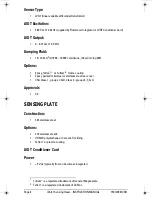
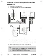
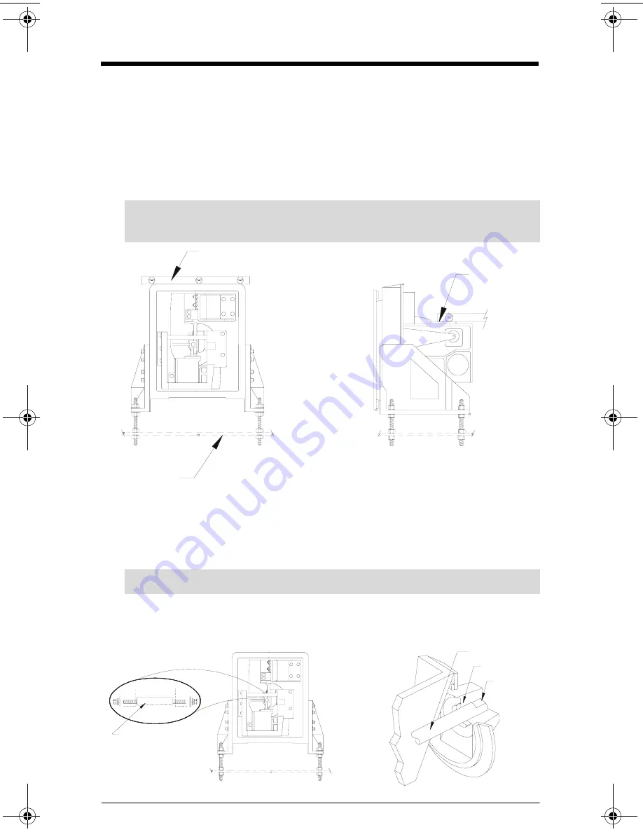
Sensing Plate
1.
Open the flowmeter housing access door.
2.
With the sensing head cover removed, remove the taper pin.
3.
Insert the sensing plate shaft fully into the sensing head socket.
4.
Insert the taper pin (flat side down), from the left side.
5.
Tighten the right taper pin nut to lock the sensing plate shaft in place.
6.
Tighten the left taper pin nut.
Note:
Ensure the sensing head mounting structure is capable of supporting the
dynamic material impact forces as well as the weight of the sensing head.
spirit level
rigid support
moving beam
(machined
surface)
Note:
Ensure the sensing plate shaft is installed with the flat side up.
taper pin
(flat side down)
shaft
socket
flat side up
376draft1.fm Page 6 Wednesday, November 21, 2001 1:54 PM
Summary of Contents for ILE-61
Page 1: ...ILE 61 SENSING HEAD November 2001 LE 61 SEINSIING HEA Instruction Manual PL 376...
Page 24: ......
Page 25: ...Notes...
Page 26: ...Notes...
Page 27: ......
Page 28: ...7ML19981CX01...


