

PL-543
10
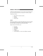
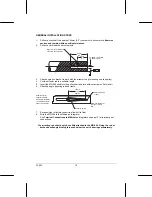
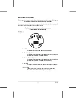
GENERAL INSTALLATION STEPS
1.
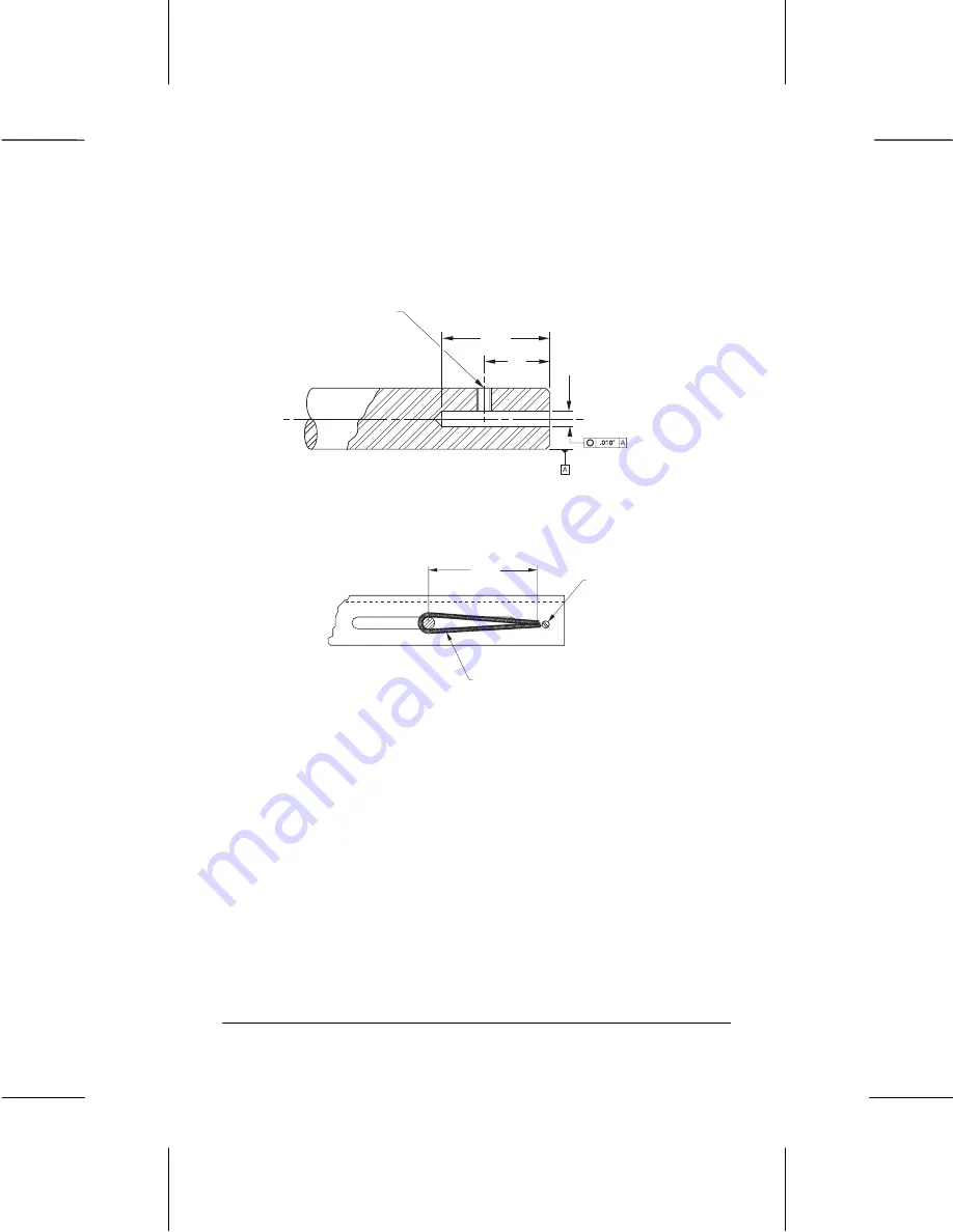
Drill out pulley shaft to a depth of 64mm (2.5”) concentric to its centerline. Exercise
caution and remain within specified tolerances.
2.
Drill out and thread the set screw hole
3.
Attach angle iron bracket to work with the arrestor rod (if mounting on a tail pulley)
4.
Cut the arrestor rod to a suitable length
5.
Insert the MD-256 shaft into the pulley shaft and lock with set screw on flat of shaft
6.
Attach spring to arresting rod and frame
7.
Encase wiring in flexible conduit to allow unit to float
8.
Wire the MD-256 to the Milltronics’ integrator
See Terminal Connections to Milltronics Integrators on page 12 for terminal post
connections
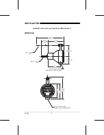
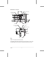
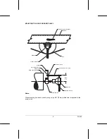
The arresting rod should only be solidly attached to the MD-256. Fixing the rod at
both ends will apply binding forces and wear the unit’s bearings prematurely.
127mm
(5”)
approx.
Tension spring
Secure with bolt
or post
Angle iron bracket or
conveyor stringer
web
Example slot for
arrestor rod when
mounted to tail pulley
– use drilled hole for
snub or bend pulley
M8x1.25 (5/16-18 UNC)
set screw (by customer)
64mm
(2.5”)
25mm
(1”)
16.00mm (.630”) DIA.
16.07mm (.633”)


