
11
PL-543
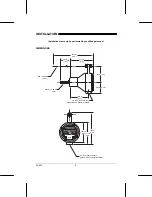
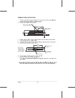
INTERCONNECTION (WIRING)
All wiring must be done in conjunction with approved conduit, boxes and fittings and
to procedures in accordance with all governing regulations.
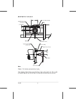
Interconnection between the unit and the integrator should be made with 3-wire shielded, 18
AWG cable. Ground the shield at the integrator end ONLY.
Flexible conduit is recommended so that excess stress
is not applied to the shaft bearings.
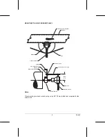
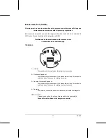
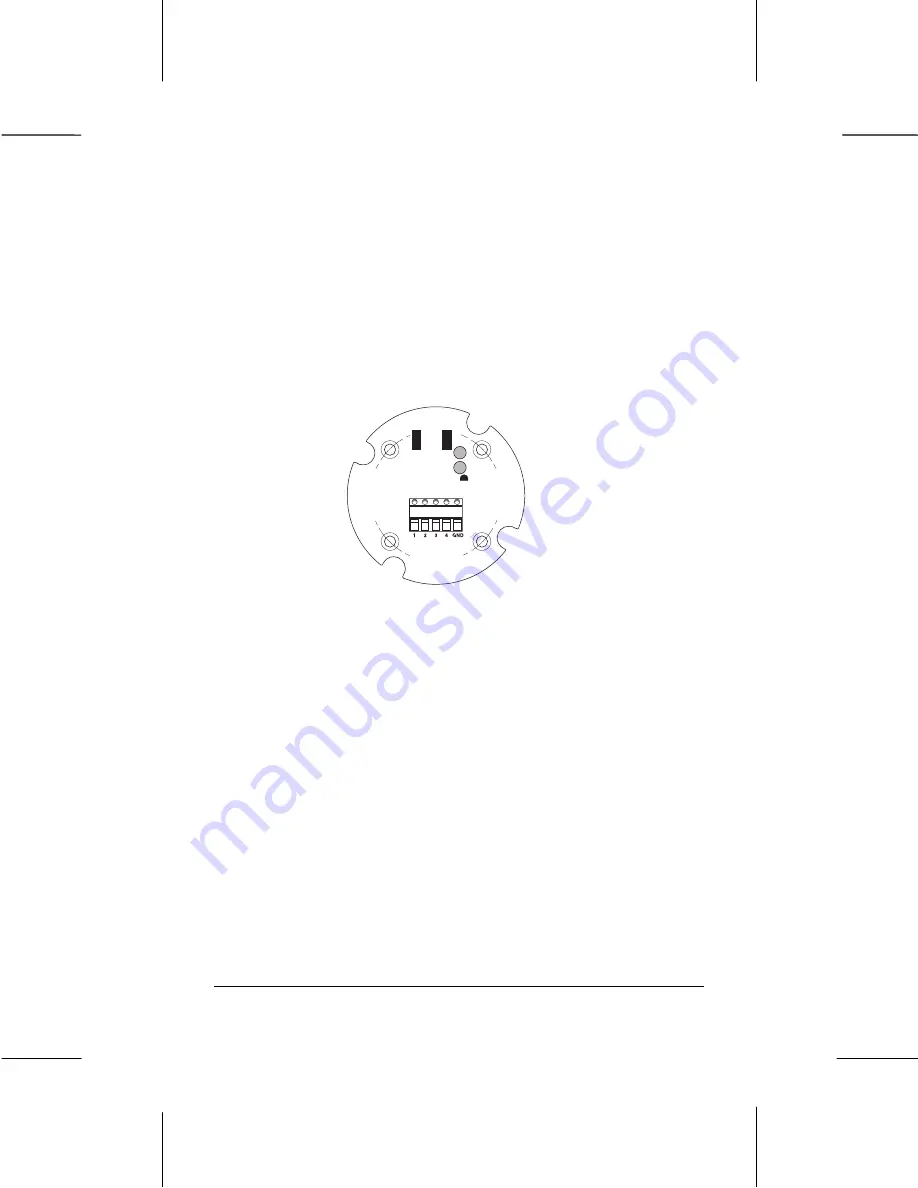
TERMINALS
1 – +15V dc
The positive power supply from the integrator connection
2 – Clockwise Speed out
The positive output connection of the measurement loop. This output is
only used when the sensor is rotating clockwise.
3 – Counter-Clockwise Speed out
The positive output connection of the measurement loop. This output is
only used when the sensor is rotating counter-clockwise.
4 – Common
The common connection used as a reference point with the integrator
GND – Ground
A ground connection. Do not use this ground for the cable shield.
Ground the cable shield at the integrator end only!


