background image

PL-543

14

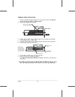
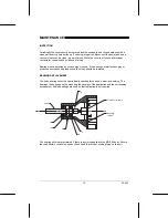
Replacement Procedure

To replace the bearings when they are worn follow these steps.

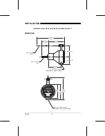
Removing the Bearings

1. 

Remove the MD-256 cover

2. 

Remove the wiring from the terminal block

3. 

Remove the unit from its installation

4. 

Unscrew the circuit board fixing screws

5. 

Remove the circuit board and store in a static-free bag or equivalent “safe” area.

6. 

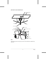
Remove the first bearing’s C clip (part A) using retaining ring pliers

7. 

Gently drift the unit’s shaft out of the housing. One bearing should come with the shaft
and one should remain in the housing.

8. 

Pull the bearing off the shaft

9. 

Drift out the bearing and rawhide seal (part F) from the housing

10.  Clean the housing with a rag

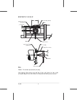
Replacing the Bearings

1. 

Warm the housing in hot water to expand the metal

2. 

Remove from the water and completely dry with a clean rag

3. 

Insert the rawhide seal (part F) into the housing

4. 

Slide one of the new bearings (part D) into the housing. Ensure it fits snugly against
the end of the housing

5. 

Slide the second bearing onto the unit’s shaft

6. 

Gently drift the shaft back into place. It is in place when you can see the groove for the
C clip (part A). Do not damage the pin on the end of the shaft as that is required to turn
the encoder.

7. 

Replace the C clip (part A)

8. 

Replace the circuit board and ensure correct alignment of the rubber coupling and the
shaft pins.

9. 

Replace the mounting screws for the circuit board

10.  Reconnect to the installation
11.  Rewire the terminal block
12.  Replace the MD-256 cover
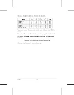
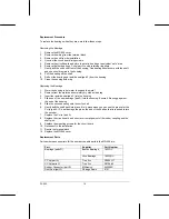
Replacement Parts

Part numbers and suppliers for the user-serviceable parts in the MD-256 are:

Part

Supplier

Part Number

Boston Bearings,

1623DC

Bearings (parts D)

Nice Bearings

16232RS

C Clip (part A)

True Arc

R3000-137

C Clip (parts C)

True Arc

R3100-62

Rubber Connector (part E)

Milltronics

24300051

Dust Seal (part F)

Chicago Seals

6141

Summary of Contents for MD-256

Page 1: ...MD 256 Speed Sensor April 1998 Instruction Manual PL 543 33455430 Rev 1 0...

Page 2: ...de ultrasonic and capacitance level measurement in line weighing of dry bulk solids and motion sensing Milltronics is established world wide through associate offices and representatives Our network i...

Page 3: ...uit 5 Installation 6 Dimensions 6 Mounting 7 Mounting to a Tail Pulley 8 Mounting to a Bend or Snub Pulley 9 General Installation Steps 10 Interconnection Wiring 11 Terminals 11 Terminal Connections t...

Page 4: ...F Input Shaft rotation 0 5 to 470 rpm bidirectional Output Unidirectional open collector sinking output 5V dc 25mA max to integrator 256 pulses per revolution 2 to 2000Hz Enclosure General purpose Al...

Page 5: ...Light weight Long bearing life CIRCUIT 256 pulses are generated for each rotation of the MD 256 shaft These pulses are typically fed into a Milltronics belt scale integrator The integrator interprets...

Page 6: ...ed personnel DIMENSIONS Rod 8 0mm 5 16 305mm 12 0 89mm 3 5 60mm 2 38 1 2 NPT conduit entrance optional PG13 5 adapter available 1 2 NPT conduit entrance optional PG13 5 adapter available Shaft 15 9mm...

Page 7: ...y attached to the MD 256 Fixing the rod at both ends will apply binding forces and cause the unit s bearings to wear prematurely When mounting the unit ensure that it is concentric with the pulley sha...

Page 8: ...play on the arrestor rod If the arrestor rod is pushed against the end of its travel slot then premature bearing wear may result d Angle bracket slotted for arrestor rod Tension spring supplied Flexi...

Page 9: ...pulley only a 3 8 10mm drilled hole is required for the arrestor rod Tension spring supplied Stringer Belt Flexible conduit MD 256 Stringer 3 8 drilled hole for arrestor rod Bend or Snub pulley Tensio...

Page 10: ...g rod and frame 7 Encase wiring in flexible conduit to allow unit to float 8 Wire the MD 256 to the Milltronics integrator See Terminal Connections to Milltronics Integrators on page 12 for terminal p...

Page 11: ...the shaft bearings TERMINALS 1 15V dc The positive power supply from the integrator connection 2 Clockwise Speed out The positive output connection of the measurement loop This output is only used whe...

Page 12: ...ss BW 100 8 7 7 6 N C Determine the pulley shaft rotation on the end of the pulley shaft to which the MD 256 is attached If the pulley shaft is rotating clockwise then connect the appropriate wire to...

Page 13: ...arings exhibit excess play or produce an unreasonably loud sound then they should be replaced BEARING REPLACEMENT The unit s bearings should be periodically checked for corrosion wear and seizing The...

Page 14: ...ean rag 3 Insert the rawhide seal part F into the housing 4 Slide one of the new bearings part D into the housing Ensure it fits snugly against the end of the housing 5 Slide the second bearing onto t...

Reviews: