C
HAPTER
4 - I
NSTALLATION
31
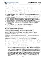
Level the Machine
(Refer to the next section for details concerning taper adjustment)
1. Center the saddle within the Z axis travel
2. Place a precision level length wise on the cross slide then level the machine head to
tail using the outer most footpads (4 corners).
3. Adjust the remaining footpads to contact the floor.
4. Place the level on the ground surface of the saddle running perpendicular to the Z
axis way surface.
5. Move the Z axis the full length of the travel while adjusting the footpads to eliminate
any twist in the bed.
6. Check that all footpads have full contact on the floor, then tighten the jam nuts.
7. Turn a part without using the tail stock, then check the part for taper. .0002” per ft.
(.005mm per 300mm) is the specification for maximum allowable taper.
8. Adjust the head stock to remove taper if found by loosening the mounting bolts and
adjusting the bolts, found on the back side of the head stock (behind mag box).
Repeat step 7.
9. Check side to side adjustment of tail stock and adjust if necessary.
ML Lathe Head Stock Taper Specification
(Refer to this text while leveling the machine in the startup checklist)
Milltronics ML lathe products have a
.0002 inch per foot
(.005mm per 300mm)
specification for head stock taper.
In almost all cases action will be required at the time of setup to adjust the lathe into
tolerance.
The first step in the process is to level the machine. The bed should be as level as
possible and should be checked for twist. Check for twist is laying a precision level
along the cross slide and moving the Z axis back and forth slowly, watching the bubble
for movement. If the lathe is to be bolted to the floor, level and twist must be checked
after
the lathe is bolted down.
Checking for head stock taper can be done several ways.
By making a cut on a bar and measuring it for taper. This method works well and
is the easiest to set up. It does not require the stock be dialed in as the cut will
make it concentric. Quality of the cut and tooling pressure can have an effect on
the measurements, however, and need to be minimized for an accurate reading.
By inserting a ground bar into the chuck of the lathe and check along its length
with an indicator. The bar must be dialed in for concentricity to the spindle on
both ends before checking for taper. This may prove difficult with a three-jaw
chuck.
Summary of Contents for ML Series
Page 2: ......
Page 4: ......
Page 6: ......
Page 20: ......
Page 23: ...CHAPTER 2 SPECIFICATION ML14 26 Series Machine Layout 17 ...
Page 24: ...ML35 40 Series Machine Layouts ML35 Series ML40 Series 18 ...
Page 33: ...CHAPTER 3 SITE PREPARATION 27 ML22 ML26 Lifting device drawing ...
Page 34: ......
Page 74: ......
Page 76: ......
Page 78: ......
Page 80: ......
Page 82: ......
Page 83: ......


