W
ARRANTY
I
NITIATION
D
OCUMENTS
S
ERVING THE
M
ETAL
C
UTTING
I
NDUSTRY
S
INCE
1973
1400 M
ILL
L
ANE
•
W
ACONIA
•
MN 55387
T
EL
: 952.442.6455
•
F
AX
: 952.442.6457
www.milltronics.net
Turret (optional)
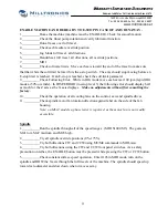
Check for proper home position and rotation direction
1.
MDI - tool change tool # 1 (M6 T0101)
2.
Check the turret position (it should be #1)
3.
Advance the turret from pocket #1 to #2 (MDI M6 T02 T02) Switch phasing of input
power if direction is incorrect.
Installing the chuck
1.
Clean all surfaces of the chuck and the spindle face.
2.
Set the chuck on the spindle using the cam locks
3.
Turn the cam locks clockwise making sure the “V” mark on cam locates between the
2 “V” marks on the housing
Level the machine
(refer to pages 27 in the instruction handbook for details concerning taper adjustment)
1.
Center the saddle within the Z axis travel
2.
Place a precision level length wise on the cross slide then level the machine head to
tail using the outer most footpads (4 corners).
3.
Adjust the remaining footpads to contact the floor.
4.
Place the level on the ground surface of the saddle running perpendicular to the Z axis
way surface.
5.
Move the Z axis the full length of the travel while adjusting the footpads to eliminate
any twist in the bed.
6.
Check that all footpads have full contact on the floor, then tighten the jam nuts.
7.
Turn a part without using the tail stock, then check the part for taper. .0002” per ft. is
the specification for maximum allowable taper.
8.
Adjust the head stock to remove taper if found by loosening the mounting bolts and
adjusting the bolts, found on the back side of the head stock (behind mag box). Repeat
step 7.
9.
Check side to side adjustment of tail stock and adjust if necessary.
4
Summary of Contents for ML Series
Page 2: ......
Page 4: ......
Page 6: ......
Page 20: ......
Page 23: ...CHAPTER 2 SPECIFICATION ML14 26 Series Machine Layout 17 ...
Page 24: ...ML35 40 Series Machine Layouts ML35 Series ML40 Series 18 ...
Page 33: ...CHAPTER 3 SITE PREPARATION 27 ML22 ML26 Lifting device drawing ...
Page 34: ......
Page 74: ......
Page 76: ......
Page 78: ......
Page 80: ......
Page 82: ......
Page 83: ......


