C
HAPTER
4 - I
NSTALLATION
Safety Checks
Follow the sequences outlined below.
Home the Machine
During this operation, the machine will move. Before starting the operation,
make sure any shipping clamps that might impede machine movement have
been removed and nothing else remains to interfere with machine motion. On
Milltronics lathes, the Z axis homes in the center of travel.
Turn main power on.
Press the green
ENABLE
button to power up the servos. Note: If the machine
does not ENABLE, check all emergency stop switches: conveyor, remote hand
controller, etc. then try to enable the drives again.
Press
F1
(Home).
Press
CYCLE START.
During the sequence outlined below, the spindle will rotate. If there is a tool in
the spindle (for mills) or if there is a workpiece in the spindle (for lathes), make
sure it is not going to hit anything when the spindle turns. For lathes, the chuck
guard must be down. If the machine has an enclosure, close the door.
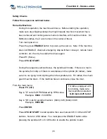
From the main menu:
For lathes equipped with
live tooling, make sure
main spindle is selected.
G24 main, G25 turret
Press
F5
(MDI).
Key in "S" code for RPM followed by RPM value.
Example:
S500
= 500 RPM
Key in "M" code for spindle direction: (M03)=CW, (M04)=CCW
Example:
S500 M3
Press
ENTER.
Press
CYCLE START
to start spindle, then use manual CW, CCW and STOP
buttons. Note for 7200 lathes: You must press the ENABLE button while
pressing the spindle CW or CCW button to enable the spindle to start.
35
Summary of Contents for ML Series
Page 2: ......
Page 4: ......
Page 6: ......
Page 20: ......
Page 23: ...CHAPTER 2 SPECIFICATION ML14 26 Series Machine Layout 17 ...
Page 24: ...ML35 40 Series Machine Layouts ML35 Series ML40 Series 18 ...
Page 33: ...CHAPTER 3 SITE PREPARATION 27 ML22 ML26 Lifting device drawing ...
Page 34: ......
Page 74: ......
Page 76: ......
Page 78: ......
Page 80: ......
Page 82: ......
Page 83: ......


