Although the accepted tolerance for idler alignement is
±
0.8 mm (1/32"), the scale mounted idlers should
never be lower than the adjacent idlers. Establishing good idler alignment is the most important part of the
installation procedure. Scale accuracy is directly affected by alignment. Proper attention must be given here.
CALIBRATION
GENERAL
After the MMI-2 has been properly installed, calibration of the weighing system must be done in conjunction
with the integrator. Refer to the integrator instruction manual for programming and calibration. The
calibration is initially done using the supplied test load. Material tests are recommended to achieve maximum
accuracy.
TEST LOAD
The test load value for each MSI is the same and is given on the accompanying data sheet. The value is to
be entered into the dedicated programming parameter of the integrator, in kilograms per meter or pounds per
feet. An equal number and mass of weights must be applied to each suspension during the span calibration
function.
If the actual idler spacing differs from that recorded on the design data sheet, the test load must be
recalculated as follows. Failure to do so will cause the design test load value to be in error.
test load =
total weight of all test weights per MSI kg
lb
idler spacing
m
ft
ZERO
Perform the zero calibration as described in the Calibration section of the integrator manual.
SPAN
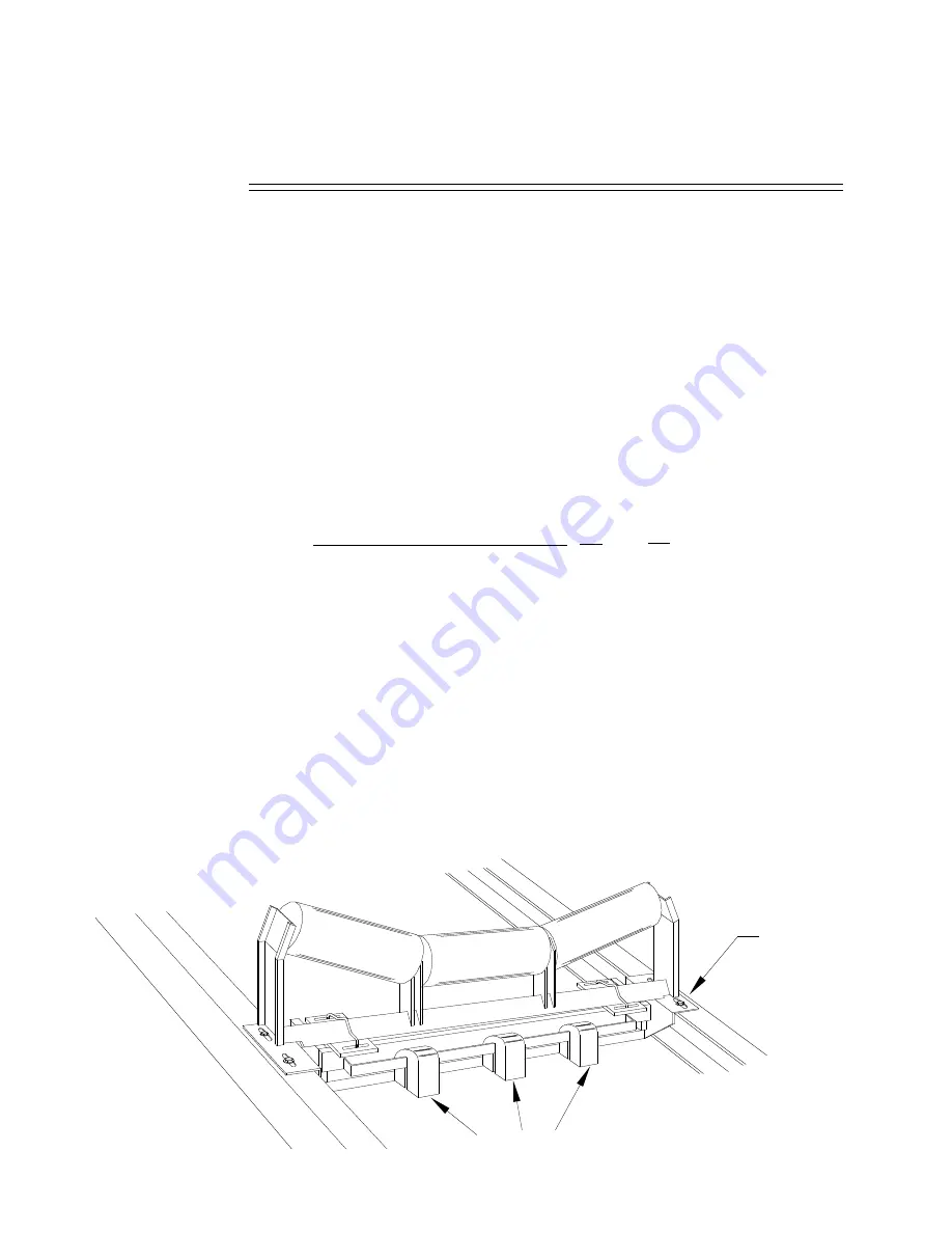
The test load used in the calibration procedure is the two sets of test weights ( 1 to 12 ) supplied, one for each
MSI suspension.
Place each set of the test weights onto the calibration weight bar of the respective MSI as shown.
Perform the span calibration as described in the Calibration section of the integrator instruction manual.
After the span calibration has been completed, remove the test load and store it.
( ) ( )
OR
test weight(s)
MSI
PL-327
8


