background image

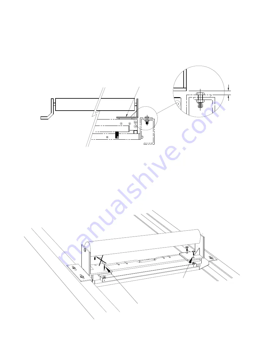
FLAT IDLER 

idler modification

idler installation

12.7mm
(0.5")

before

after

customer’s idler

in most applications standard
conveyor manufacturers’
brackets cannot be used,
replacement brackets 
(as shown) are needed

idler clip

customer bolts
  (4 places)

PL-327

12

Summary of Contents for MMI-2

Page 1: ...MMI 2 2 IDLER BELT SCALE Instruction Manual PL 327 January 2001 MMI 2 BELT SCALE 33453270 Rev 2 3 ...

Page 2: ...on and in electronic version We encourage users to purchase authorized bound manuals or to view electronic versions as designed and authored by Siemens Milltronics Process Instruments Inc Siemens Milltronics Process Instruments Inc will not be responsible for the contents of partial or whole reproductions of either bound or electronic versions While we have verified the contents of this manual for...

Page 3: ... Load Cell Handling 4 Installation Procedure 5 CALIBRATION General 8 Test Load 8 Zero 8 Span 8 Material Test 9 Re Rating 9 MAINTENANCE AND SPARE PARTS 9 IDLER MOUNTING Troughed Idler with Channel Spine 10 Troughed Idler with Pipe Spine 11 Flat Idler 12 MSI WIRING 13 OUTLINE DIMENSIONS CEMA 14 OUTLINE DIMENSIONS METRIC 15 PL 327 i ...

Page 4: ... bulk solids Each MSI is comprised of the following one weighbridge c w two load cells with cables run in a common flexible conduit test weight s The addition of an idler supplied and installed by customer to each weighbridge completes the weighing assembly The MMI load cells provide an electronic signal proportional to load which is fed to the Milltronics CompuScale series integrator Thus weighin...

Page 5: ...er 50 to 180 mm 2 to 7 Idler Spacing 0 5 to 1 5 m 1 5 to 5 0 ft Load Cell excitation 10 V DC nominal 15 V DC maximum output 2 mV V excitation at rated load cell capacity non linearity 0 02 of rated output hysteresis 0 02 of rated output non repeatability 0 01 of rated output capacity maximum ranges 50 100 250 500 750 1000 lb overload maximum 1000 of rated capacity temperature 40 to 85 C 40 to 185 ...

Page 6: ...supports the scale idler and transfers the weight of the material to the load cells These are the active components in the weighing assembly As the material travels along the conveyor a force is exerted through the suspended idler onto the weighing assembly The weighing assembly is forced down proportionally The movement in each load cell is sensed by its strain gauges These modulate the excitiati...

Page 7: ...s provided or by reference to Milltronics instruction manual PL 328 Applications Guidelines WELDING Extreme caution should be used when arc welding in the area of the belt scale Insure that no welding current can flow through the belt scale Welding currents through the scale are sufficient to functionally destroy the load cells LOAD CELL HANDLING The load cell can tolerate very little negative dis...

Page 8: ...e the existing holes in the stringer and should not require further drilling Install the mounting bolts and nuts but do not tighten Remove the idler clips Refer to Outline and Dimensions Insure that there is sufficient clearance between the return belt and the MSI and test weight when used during the calibration procedure 12 7 mm 0 5 before 100 mm 4 after customer s idler MSI belt scales location ...

Page 9: ...arrangements Orient the scale so that the large arrow on the scale mounting brackets is pointing in the direction of material flow 5 Release the shipping stops on each MSI in order to free the weighing mechanism Loosen screws A and rotate both shipping stops inward until the underside slots slide around the shoulder bolts B Tighten screws A to secure in place idler clips conveyor stringer typical ...

Page 10: ...being applied on each idler in the weighing area causing calibration and measurement errors Use a good quality wire or string to check for alignment The wire or string must be able to withstand sufficient tension as to eliminate any sag By shimming make the necessary adjustments to bring all the rolls of the A2 through to the R2 idlers in line within 0 8 mm 1 32 S 2 MSI with modified scale idler R...

Page 11: ... programming parameter of the integrator in kilograms per meter or pounds per feet An equal number and mass of weights must be applied to each suspension during the span calibration function If the actual idler spacing differs from that recorded on the design data sheet the test load must be recalculated as follows Failure to do so will cause the design test load value to be in error test load tot...

Page 12: ...ications should be referred to your local Milltronics office to insure that proper design parameters are maintained MAINTENANCE AND SPARE PARTS Each weighbridge should be kept clean Accumulations of material between the weighing assembly and static assembly as well as around each load cell can be detrimental to the weighing accuracy Periodically check the mechanical integrity of the scale and alig...

Page 13: ... in the Installation Procedure uses an angle iron spine The following depicts alternate idler construction and tips on how they should be modified and installed TROUGHED IDLER WITH CHANNEL SPINE idler modification idler installation 100 mm 4 12 7 mm 0 5 before after customer s idler gusset reinforcement if required see Installation Procedure foot pads welded to idler spine idler clip customer bolt...

Page 14: ...TROUGHED IDLER WITH PIPE SPINE idler modification idler installation foot pads welded to idler spine 100 mm 4 12 7 mm 0 5 before after customer s idler idler clip customer bolts 4 places PL 327 11 ...

Page 15: ...tion idler installation 12 7mm 0 5 before after customer s idler in most applications standard conveyor manufacturers brackets cannot be used replacement brackets as shown are needed idler clip customer bolts 4 places PL 327 12 ...

Page 16: ...DETAIL A see detail A conduit and connector load cell A belt travel belt travel load cell B load cell A C load cell B D MSI 1 load cell A load cell B load cell A load cell B customer junction box to integrator to integrator E X E E X E S I G A S I G A S I G B S I G B S H I E L D PL 327 13 ...

Page 17: ...width B 18 27 24 5 9 5 5 5 82 lb 20 29 26 5 9 5 5 5 85 lb 24 33 30 5 9 5 5 5 90 lb 30 39 36 5 9 5 5 5 99 lb 36 45 42 5 9 5 5 5 107 lb 42 51 48 5 9 5 5 5 116 lb 48 57 54 5 12 8 162 lb 54 63 60 5 12 8 174 lb 60 69 66 5 12 8 185 lb 72 81 78 75 12 8 235 lb 84 93 90 75 12 8 261 lb 96 105 102 75 12 8 288 lb PL 327 14 ...

Page 18: ...800 mm 1090 mm 1027 mm 241 mm 140 mm 48 kg 1000 mm 1240 mm 1177 mm 241 mm 140 mm 52 kg 1000 mm 1290 mm 1227 mm 305 mm 203 mm 73 kg 1200 mm 1450 mm 1387 mm 305 mm 203 mm 78 kg 1200 mm 1540 mm 1477 mm 305 mm 203 mm 83 kg 1400 mm 1650 1740 mm 1587 1677 mm 305 mm 203 mm 88 kg 1600 mm 1900 1940 mm 1837 1877 mm 305 mm 203 mm 93 kg 1800 mm 2100 2140 mm 2037 2077 mm 305 mm 203 mm 98 kg 2000 mm 2300 2340 m...

Page 19: ...nc 1954Technology Drive P O Box 4225 Peterborough ON Canada K9J 7B1 Tel 705 745 2431 Fax 705 741 0466 www milltronics com Siemens Milltronics Process Instruments Inc 2001 Subject to change without prior notice Printed in Canada c 7ML19981dr01 ...

Reviews: