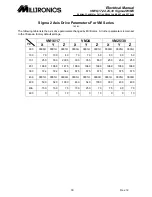

Electrical Manual
VM16,17,24,25,30 Sigma2 W/M5
S
ERVING
Y
OUR
M
ETAL
C
UTTING
N
EEDS FOR
M
ORE
T
HAN
25 Y
EARS
34 Rev.12
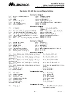
Centurion 6 CNC Connector Signal Listing
Pin 2 - Tool changer arm in/ pot down (jumpered to TCH-1)
Pin 9 - Gear 1 of 4 Gear
Pin 3 - Power drawbar (jumpered to TCH-2)
Pin 10 - Low range - Gear 2 of 4
Pin 4 - Tool carousel clockwise (jumpered to TCH-3)
Pin 11 - Medium range – Gear 3 of 4
Pin 5 - Tool carousel counter clockwise (jumpered to TCH-4)
Pin 12 - High range - Gear 4 of 4
Pin 6 - Spindle enable
Pin 13 - Key
Pin 7 - Orient roller (jumpered to TCH-5)
Pin 14 - No connect
Connector Z-Output
Pin 1 - MC1G / Optical Probe On
Pin 8 - Miscellaneous M-code No. 2
Pin 2 - MC1D / Hard Tap (For no ramps on
CSM)
Pin 9 - Miscellaneous M-code No. 3
Pin 3 - MC1C / Auger for Chip removal
M38/M39
Pin 10 - Miscellaneous M-code No. 4
Pin 4 - MC1B
Pin 11 - Miscellaneous M-code No. 5
Pin 5 - MC1A
Pin 12 - Spindle reverse
Pin 6 - Miscellaneous M-code No. 1
Pin 13 - Key
Pin 7 - End-of-cycle lamp
Pin 14 - No connect
Connector A-Output
Pin 1 - X-Axis drive enable (jumpered through JS3 to X-axis 13)
Pin 8 - Spare
Pin 2 - Y-Axis drive enable (jumpered through JS3 to Y-axis 13)
Pin 9 - Spare
Pin 3 - Z-Axis drive enable (jumpered through JS3 to Z-axis 13)
Pin 10 – Spindle Running
Pin 4 - A-Axis drive enable (jumpered through JS3 to A-axis 13)
Pin 11 – Door Open
Pin 5 - B-Axis drive enable (jumpered through JS3 to B-axis 13)
Pin 12 – Door Close
Pin 6 - Axis drives enable
Pin 13 - Key connect
Pin 7 - Arm (on Swing-Arm TlChngr)
Pin 14 - No
Connectors X, Y, Z, A and B Axis (DC Brush Drives)
Pin 1 - Channel A +
Pin 8 - +5 VDC
Pin 2 - Channel A -
Pin 9 - Axis fault/OK (jumpered through JS3 to A-Input)
Pin 3 - Channel B +
Pin 10 - Axis home switch (also found on Home Connector)
Pin 4 - Channel B -
Pin 11 - Axis analog signal
Pin 5 - Marker -
Pin 12 - Axis analog ground
Pin 6 -
Pin 13 - Axis Enable/Disable (jumpered through JS3 to A- Output)
Pin 7 - DC ground
Pin 14 - Key
Connectors X, Y, Z, A and B Axis
(Yaskawa Brushless Drives)
Pin 1 - 0 VDC
Pin 20 - Marker -
Pin 34 - Channel A -
Pin 2 - 0 VDC
Pin 29 - Servo ready
Pin 35 - Channel B +
Pin 5 - Axis analog signal
Pin 30 - 0 VDC
Pin 36 - Channel B -
Pin 6 - 0 VDC
Pin 31 - Alarm output
Pin 40 - Servo ON
Pin 10 - 0 VDC
Pin 32 - 0 VDC
Pin 47 - +24 VDC
Pin 19 -
Pin 33 - Channel A +
All other pins are no connect
Axis Home Connector
Pin 1 - X-axis home switch signal (jumpered
to X-axis 10 & X-input 12)
Pin 8 - A-axis home switch ground
Pin 2 - X-axis home switch ground
Pin 9 - B-axis home switch signal (jumpered to B-axis
10 & A-input 11)
Pin 3 - Y-axis home switch signal (jumpered
to Y-axis 10 & Y-input 12)
Pin 10 - B-axis home switch ground
Pin 4 - Y-axis home switch ground
Pin 11 - Key
Pin 5 - Z-axis home switch signal (jumpered
to Z-axis 10 & Z-input 12)
Pin 12 - No connect
Pin 6 - Z-axis home switch ground
Pin 13 - No connect
Pin 7 - A-axis home switch signal (jumpered
to A-axis 10 & A-input 12)
Pin 14 - No connect