
Electrical Manual
VM16,17,24,25,30 Sigma2 W/M5
S
ERVING
Y
OUR
M
ETAL
C
UTTING
N
EEDS FOR
M
ORE
T
HAN
25 Y
EARS
35 Rev.12
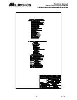
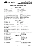
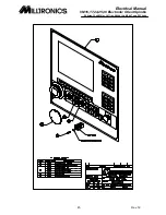
Centurion 6 CNC Connector Signal Listing
Spindle Drive Connector
Pin 1 - Forward Run (jumpered to X-out 4)
Pin 8 - Spindle analog signal (jumpered to Misc-13)
Pin 2 - Reverse Run (jumpered to X-out 5)
Pin 9 - Spindle fault contacts (jumpered to X-in 9)
Pin 3 - Ground
Pin 10 - Ground
Pin 4 - Key
Pin 11 - Spindle analog signal ground (jumpered to
Misc-14)
Pin 5 - Creep speed (jumpered to Y-out 1)
Pin 12 - Spindle load meter (jumpered to Misc-3)
Pin 6 - Ground
Pin 13 - Up-to-speed (jumpered to X-in 4)
Pin 7 - Ground
Pin 14 - Zero speed (jumpered to X-in 8)
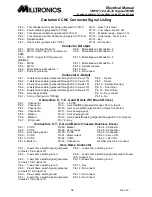
Spindle Encoder Connector
Pin 1 - Channel A +
Pin 6 -
Pin 11 - DC ground
Pin 2 - Channel A -
Pin 7 - DC ground
Pin 12 - DC ground
Pin 3 - Channel B +
Pin 8 - +5 VDC
Pin 13 - DC ground
Pin 4 - Channel B -
Pin 9 - DC ground
Pin 14 - Key
Pin 5 - Marker -
Pin 10 - No connect
Miscellaneous Connector (Misc)
Pin 1 - Machine reset - CR1C (+24 VDC)
Pin 8 - Reset 2 (jumpered to FPP-8)
Pin 2 - Machine reset - K1 coil
Pin 9 - Tool change 1
Pin 3 - Load meter analog
Pin 10 - Tool change 2
Pin 4 - DC ground
Pin 11 - E-stop 1
Pin 5 - Key
Pin 12 - E-stop 2
Pin 6 - Excess error latch
Pin 13 - Spindle analog
Pin 7 - Reset 1 (jumpered to FPP-7)
Pin 14 - DC ground
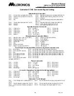
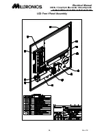
Front Panel Connector (FPP) and J2 on keyboard encoder card
Pin 1 - No connect
Pin 8 - Front panel reset switch (jumpered to Misc-8)
Pin 2 - Front panel DC ground
Pin 9 - Front panel tool change reset switch (jumpered to Misc-9)
Pin 3 - Key
Pin 10 - Front panel tool change reset switch (jumpered to Misc-10)
Pin 4 - Front panel +24 VDC
Pin 11 - Front panel emergency stop switch (jumpered to Misc-11)
Pin 5 - Front panel +12 VDC
Pin 12 - Front panel emergency stop switch (jumpered to Misc-12)
Pin 6 - No connect
Pin 13- No connect
Pin 14 - No connect
Pin 7 - Front panel reset switch
(jumpered to Misc-7)
Power Connector
Pin 1 - +5 VDC
Pin 6 - +12 VDC
Pin 11 - DC ground
Pin 2 - +5 VDC
Pin 7 - -12 VDC
Pin 12 - DC ground
Pin 3 - +5 VDC
Pin 8 - No connect
Pin 13 - DC ground
Pin 4 - +24 VDC
Pin 9 - Key
Pin 14 - DC ground
Pin 5 - No connect
Pin 10 - DC ground
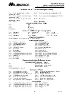
Connector Handwheel
for remote handwheel option
Pin 1 - Channel A +
Pin 6 - No connect
Pin 11 - DC ground
Pin 2 - Channel A -
Pin 7 - DC ground
Pin 12 - DC ground
Pin 3 - Channel B +
Pin 8 - +5 VDC
Pin 13 - DC ground
Pin 4 - Channel B -
Pin 9 - DC ground
Pin 14 - Key
Pin 5 - No connect
Pin 10 - No connect
Connector Tool Changer
Pin 1 - Tool changer arm in (jumpered to Y-
out 2)
Pin 8 - Tool carousel at home prox (jumpered to Y-in 2)
Pin 2 - Power drawbar (jumperd to Y-out 3)
Pin 9 - Tool carousel at pocket (jumpered to Y-in 3)
Pin 3 - Tool carousel clockwise (jumpered
to Y-out 4)
Pin 10 - Tool changer arm in(jumpered to Y-in 4)


