R
Pellerin
Milnor
Corporation
Pellerin
Milnor
Corporation
P.
O.
Box
400,
Kenner
,L
A
70063-0400
Litho
in
U.S.A.
BMP920029/98443V
(1
of
2)
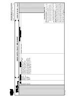
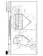
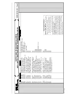
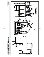
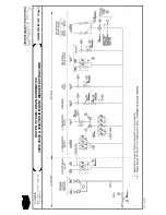
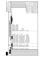
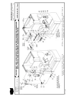
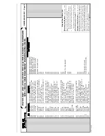
BMP920029/98443V
(Sheet
1
of
2)
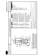
2-W
ay
Electric
W
ater
V
alv
e
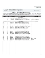
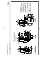
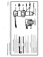
Identification
and
Description
Check
nameplate
for
correct
catalog
number,
pressure,
voltage,
and
service.
Safety
Instructions
Lock
OFF
and
tag
out
power
at
wall
disconnect
before
servicing.
Power
switches
on
machine
and
control
box
disable
only
control
circuit
power
in
electrical
boxes.
D
ANGER
SHOCK
HAZARD
will
cause
death
or
severe
injury
.
+
WARNING
CA
UTION
Release
pressure
to
valve
before
disassembly
.
EXPLOSION
HAZARD
may
cause
serious
injury
.
+
Allow
solenoids
to
cool
before
servicing
the
valves.
BURN
HAZARD
Solenoid
enclosures
become
too
hot
to
touch
when
energized
for
a
long
period.
This
will
not
damage
the
solenoid,
but
may
cause
a
painful
burn.
+
Maintenance
READ
ALL
SAFETY
ST
ATEMENTS
ABOVE
BEFORE
PROCEEDING
ANY
FURTHER!
Coil
Replacement
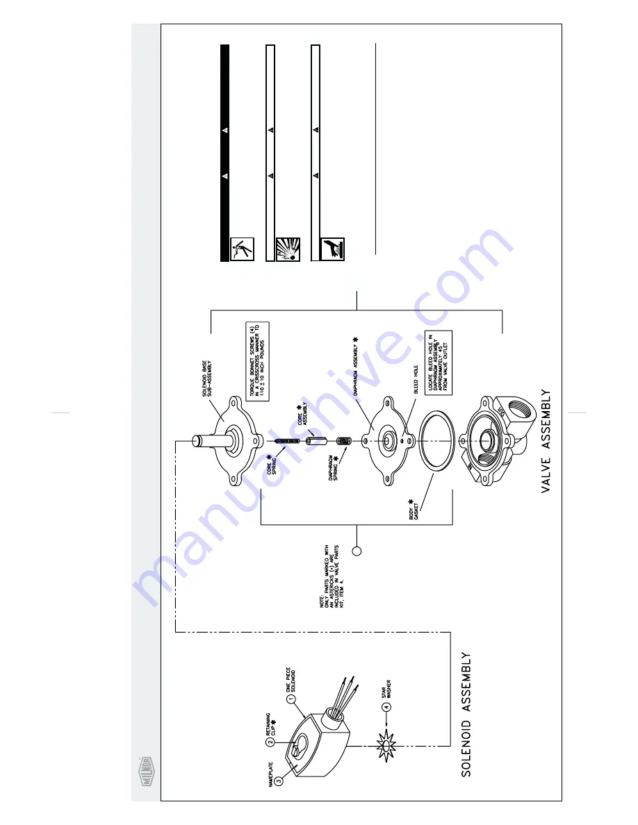
1 2 3 4
.
Remove
retaining
clip.
NOTE:
Whe
metal
retaining
clip
disengages,
it
springs
upwards.
.
Slip
yoke
containg
coil
and
sleeves
off
solenoid
base
sub-assembly.
.
Replace
coil.
.
Reassemble
in
reverse
order.
Valve
Disassembly
and
Reassembly
1 2 3 4
6
.
Remove
retaining
clip.
.
Slip
entire
solenoid
enclosure
off
the
solenoid
base
sub-assembly.
.
Remove
solenoid
base
sub-assembly,
core
assembly
and
core
spring.
.
Remove
diaphragm
spring,
diaphragm
assembly
and
gasket.
5.
Replace
all
worn
or
damaged
parts.
.
Reassemble
in
reverse
order.
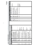
Troubleshooting
Control
Circuit
Faulty
coil
Low
voltage
Incorrect
pressure
Excess
leakage
:
Listen
for
a
metallic
click
when
energizing
the
solenoid.
Absence
of
the
click
indicates
loss
of
power
to
the
solenoid.
Check
for
loose
connections,
blown
fuses,
open
or
grounded
coil
circuit,
and
broken
lead
wires.
:
Check
for
open
circuit
in
coil.
Replace
coil
if
necessary.
:
Voltage
across
coil
leads
must
be
at
least
85%
of
nameplate
rating
for
proper
operation.
:Pressure
to
valve
must
be
within
range
specified
on
nameplate.
:
Disassemble
valve
and
clean
all
parts.
Replace
all
worn
parts
for
best
results.
00A 00B 00C
5
Summary of Contents for 30015
Page 6: ......
Page 8: ......
Page 10: ......
Page 19: ...Section 1 Service and Maintenance ...
Page 51: ...Section 2 Drive Assemblies ...
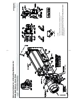
Page 59: ...BMP950003 95107V Page 1 MOTOR MOUNT 30015 30020 S4A S4G S4J S4T ...
Page 68: ......
Page 69: ...Section 3 Bearing Assemblies ...
Page 72: ...BMP910032 96141V Page 1 MAIN BEARING ASSEMBLY 30015C4x M4x K5x S5x ...
Page 74: ...BMP910033 96141V Page 1 MAIN BEARING ASSEMBLY ...
Page 76: ...BMP910034 95116V Page 1 MAIN BEARING ASSEMBLY 30015M6x ...
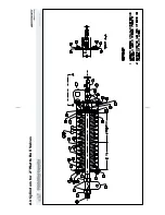
Page 80: ...BMP910035 93251V Page 1 JACKSHAFT ASSEMBLY 30015 30020 30022 RIGID MOUNT WASHER EXTRACTORS ...
Page 82: ......
Page 83: ...Section 4 Shell and Door Assemblies ...
Page 86: ...BMP920009 94491V Page 1 DOOR ASSEMBLY 30015 30020 RIGID MOUNT WASHER EXTRACTORS ...
Page 90: ......
Page 91: ...Section 5 Control and Sensing Devices ...
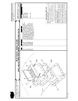
Page 100: ...BMP920010 97281V Page 1 COIN ASSEMBLY INSTALLATION 240V 30015 30020 30022 COIN MACHINES ...
Page 105: ...Section 6 Chemical Supply Devices ...
Page 113: ...Section 7 Water and Steam Piping and Assemblies ...
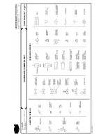
Page 114: ...ISOMETRIC SYMBOLS STANDARD SYMBOLS BMP920008 93027V Page 1 SCHEMATIC SYMBOLS KEY ...
Page 132: ...BMP920021 93251V Page 1 STEAM INSTALLATION 30015 30020 30022 RIGID MOUNT WASHER EXTRACTORS ...
Page 138: ...BMP920017 93251V Page 1 ELECTRIC DRAIN VALVE 30015 30020 30022 RIGID MOUNT WASHER EXTRACTORS ...

