MSSM0705CE/9903AV
È
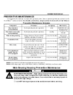
PREVENTIVE MAINTENANCE
As required by the warranty, to ensure safe operation, and to achieve optimum performance and service life
from Milnor
®
washer-extractors, the schedules, instructions, and precautions herein must be strictly followed.
Ï
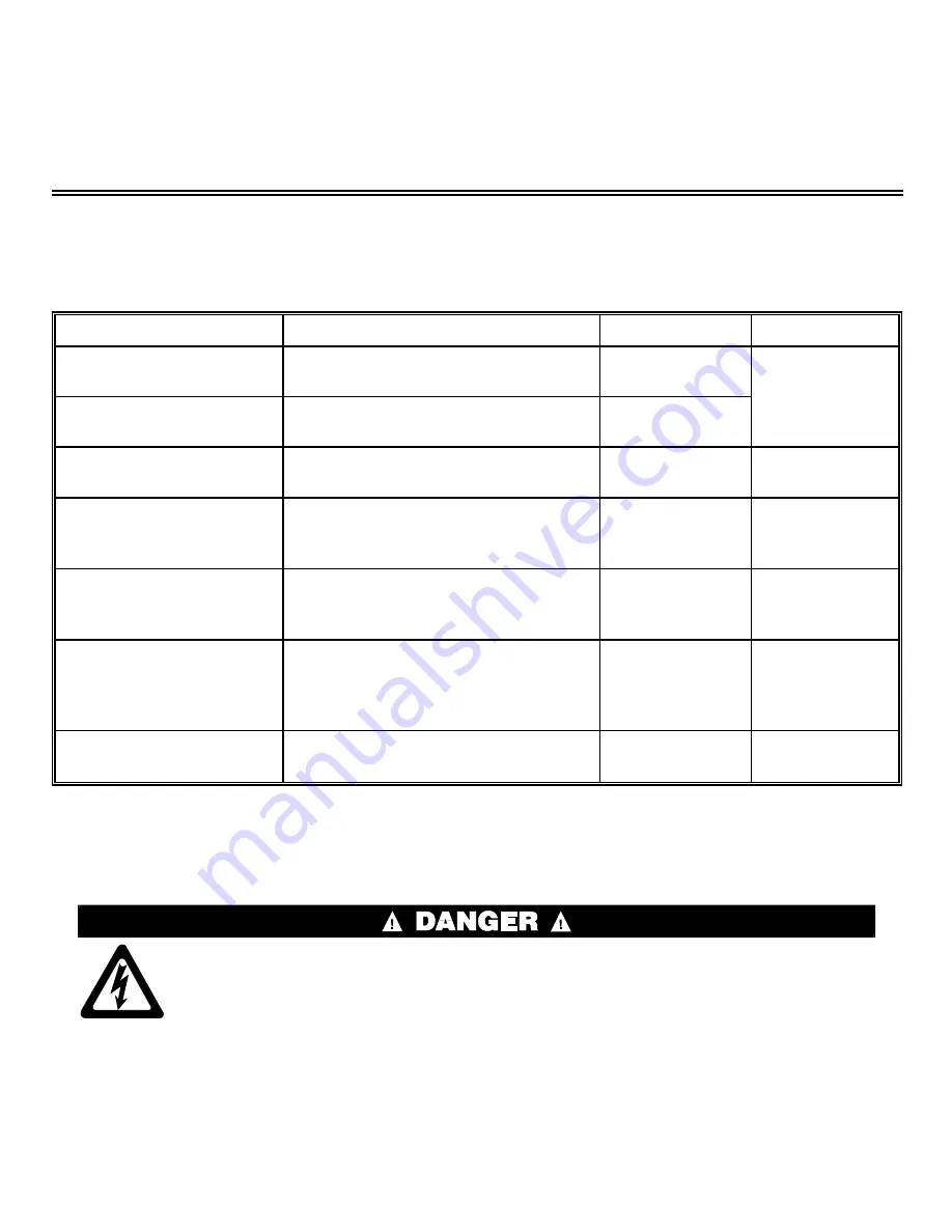
Preventive Maintenance Schedule
Component
Procedure
Frequency
Info. Source
Door interlock
(coin machines)
Test functioning for safe operation.
daily
MSOP0512AE in
Operating and
Troubleshooting
Manual
Electronic coin counter
(coin machines)
Test functioning for safe operation.
monthly
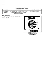
Main bearing housing
Change lubricant. Check rear bolt
tightness and adjust if necessary.
every four months
this section
(see FIGURE 1)
Foundation bolts
Check bolt tightness and wear.
Adjust or replace if necessary.
every four months
dimensional
drawing
(see NOTE 1 )
Drive train
Check belt tension and wear. Check
pulleys and other drive components
for wear. Replace if necessary.
every four months
MSSM0706BE
(see NOTE 1 )
3/5 Compartment
Supply injector
(if so equipped)
Inspect and clean strainers in water
valves, and each compartment. If rust is
detected, carefully clean it away once
each week.
every four months
BMP770149
BMP920019
(see NOTE 2)
Steam strainer
(if so equipped)
Inspect and clean strainer.
every four months
BMP920015
(see NOTE 2)
NOTE 1: See Table of Contents for information not in this section.
NOTE 2: Drawings apply only to 30015Mxx, and Sxx; 30020Mxx; 30022Mxx, and Sxx models.
Ê
Main Bearing Housing Preventive Maintenance
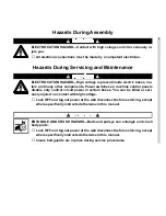
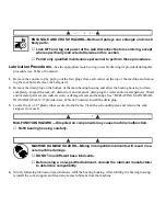
ELECTROCUTION HAZARD—High voltage is present inside electric boxes, mo-
tors, and many other components. Power switches on machine disable only
control circuit power in certain boxes. You can be killed or seriously injured on
contact with high voltage.
☞
Lock OFF and tag out power at the wall disconnect before servicing.
ENTANGLE AND CRUSH HAZARD—Belts and pulleys can entangle and crush
body parts.
☞
Lock OFF and tag out power at the wall disconnect before servicing, except
where specifically instructed otherwise in this section.
☞
Permit only qualified maintenance personnel to perform these procedures.
Ë
Lubrication Procedures
—See the appropriate main bearing assembly drawing (if provided) during this
procedure (see Table of Contents).
1. Remove the console top by prying out the four plugs from each corner on the top of the machine and remov-
ing the four bolts. Remove the belt guard.
2. Remove the drain plug on the bottom of the main bearing housing and allow the bearing housing to drain
completely. Inspect the leak-off, drained oil, and magnetic drain plug for water and/or metal particles. Water
and/or metal particles can indicate worn or damaged seals and bearings. See “REPLACING MAIN BEAR-
INGS AND SEALS,” if provided (see Table of Contents). Install the drain plug.
3. Locate the two 1/2" plastic tubes secured to the frame. Clean the surrounding area and remove the cork
stoppers from each.
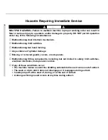
MALFUNCTION HAZARD—Oil spilled on components may cause machine malfunction.
☞
Refill bearing housing carefully.
MACHINE DAMAGE HAZARD—Mixing incompatible lubricants will result in se-
vere machine damage.
☞
DO NOT mix different base lubricants.
☞
Before using a non-specified lubricant, consult the lubricant manufacturer
to determine compatibility.
4. Strictly following lubrication specifications, refill the bearing housing. After refilling the bearing housing,
reinstall the cork stoppers and clean any excess lubricant from the machine.
Summary of Contents for 30015
Page 6: ......
Page 8: ......
Page 10: ......
Page 19: ...Section 1 Service and Maintenance ...
Page 51: ...Section 2 Drive Assemblies ...
Page 59: ...BMP950003 95107V Page 1 MOTOR MOUNT 30015 30020 S4A S4G S4J S4T ...
Page 68: ......
Page 69: ...Section 3 Bearing Assemblies ...
Page 72: ...BMP910032 96141V Page 1 MAIN BEARING ASSEMBLY 30015C4x M4x K5x S5x ...
Page 74: ...BMP910033 96141V Page 1 MAIN BEARING ASSEMBLY ...
Page 76: ...BMP910034 95116V Page 1 MAIN BEARING ASSEMBLY 30015M6x ...
Page 80: ...BMP910035 93251V Page 1 JACKSHAFT ASSEMBLY 30015 30020 30022 RIGID MOUNT WASHER EXTRACTORS ...
Page 82: ......
Page 83: ...Section 4 Shell and Door Assemblies ...
Page 86: ...BMP920009 94491V Page 1 DOOR ASSEMBLY 30015 30020 RIGID MOUNT WASHER EXTRACTORS ...
Page 90: ......
Page 91: ...Section 5 Control and Sensing Devices ...
Page 100: ...BMP920010 97281V Page 1 COIN ASSEMBLY INSTALLATION 240V 30015 30020 30022 COIN MACHINES ...
Page 105: ...Section 6 Chemical Supply Devices ...
Page 113: ...Section 7 Water and Steam Piping and Assemblies ...
Page 114: ...ISOMETRIC SYMBOLS STANDARD SYMBOLS BMP920008 93027V Page 1 SCHEMATIC SYMBOLS KEY ...
Page 132: ...BMP920021 93251V Page 1 STEAM INSTALLATION 30015 30020 30022 RIGID MOUNT WASHER EXTRACTORS ...
Page 138: ...BMP920017 93251V Page 1 ELECTRIC DRAIN VALVE 30015 30020 30022 RIGID MOUNT WASHER EXTRACTORS ...


