MSSM0101CE/9906AV (1 of 19)
È
FASTENER TORQUE REQUIREMENTS
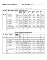
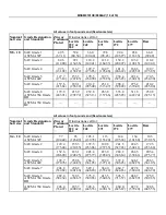
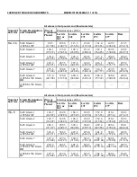
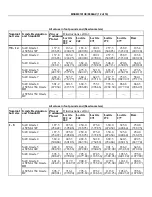
The specifications in this section apply to 1/4 inch and larger Unified National fine and coarse fasteners used on
Milnor
®
machines. This information is to be used only when torque specifications are not stated in the installation
or service instructions.
When tightening applicable fastener, abide by the follow-
ing precautions:
1. Always use new fasteners. Replace bolts, nuts, flat wash-
ers, and lock washers in the order shown on the parts
drawing.
2. Unless otherwise specified, use:
•
Loctite
®
271 threadlocker or equivalent for bearing
housing mounting bolts from one half to one inch in di-
ameter.
•
Loctite
®
277 threadlocker or equivalent for bearing
housing mounting bolts of one inch diameter or larger.
•
Loctite
®
242 threadlocker for all other fasteners
requiring thread locking compound.
3. Use a torque wrench to assure proper tightness.
4. Never lubricate fasteners. The values specified herein are
maximum recommended torques and are calculated from
published ASTM and SAE data. Actual allowable torques
are application dependent and can vary for many reasons,
(joint types, gaskets, etc.). Use these values as a guide.
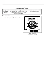
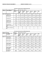
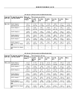
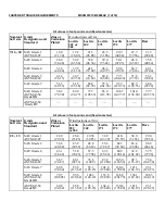
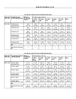
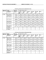
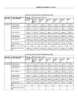
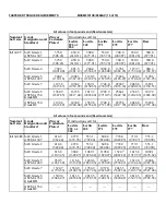
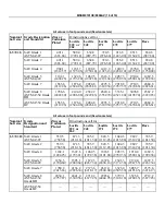
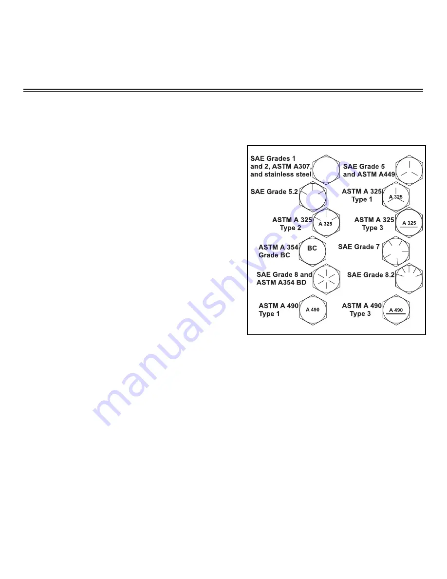
5. Although FIGURE 1 depicts hex head bolts, the table applies to all head types.
Ê
Fasteners and Threadlocker
Ë
How Fasteners Loosen
—Standard threaded fasteners are manufactured with a clearance fit for easy assem-
bly. With the fastener at the proper torque, 85% of the tightening torque is absorbed in the threads and under the
fastener head. The remaining 15% provides the friction that prevents the thread from slipping. When this friction is
overcome (by bending, thermal expansion, internal pressures, functional loads, or impact) the thread slips and loos-
ens. Although higher torques reduce the likelihood of thread slippage, if slippage occurs, the threads unwind and
the fastener loosens. Once thread slippage begins, vibration increases the rate of loosening.
Ë
Preventing Loosening
—The most effective way to prevent loosening of threaded parts is by proper appli-
cation of a threadlocking compound. Threadlocker provides lubrication during assembly, then hardens to seal the
threads against corrosion and provide resistance to thread slippage.
Î
FIGURE 1
(MSSM0101CE)
Î
Fastener Grade Markings
Summary of Contents for 30015
Page 6: ......
Page 8: ......
Page 10: ......
Page 19: ...Section 1 Service and Maintenance ...
Page 51: ...Section 2 Drive Assemblies ...
Page 59: ...BMP950003 95107V Page 1 MOTOR MOUNT 30015 30020 S4A S4G S4J S4T ...
Page 68: ......
Page 69: ...Section 3 Bearing Assemblies ...
Page 72: ...BMP910032 96141V Page 1 MAIN BEARING ASSEMBLY 30015C4x M4x K5x S5x ...
Page 74: ...BMP910033 96141V Page 1 MAIN BEARING ASSEMBLY ...
Page 76: ...BMP910034 95116V Page 1 MAIN BEARING ASSEMBLY 30015M6x ...
Page 80: ...BMP910035 93251V Page 1 JACKSHAFT ASSEMBLY 30015 30020 30022 RIGID MOUNT WASHER EXTRACTORS ...
Page 82: ......
Page 83: ...Section 4 Shell and Door Assemblies ...
Page 86: ...BMP920009 94491V Page 1 DOOR ASSEMBLY 30015 30020 RIGID MOUNT WASHER EXTRACTORS ...
Page 90: ......
Page 91: ...Section 5 Control and Sensing Devices ...
Page 100: ...BMP920010 97281V Page 1 COIN ASSEMBLY INSTALLATION 240V 30015 30020 30022 COIN MACHINES ...
Page 105: ...Section 6 Chemical Supply Devices ...
Page 113: ...Section 7 Water and Steam Piping and Assemblies ...
Page 114: ...ISOMETRIC SYMBOLS STANDARD SYMBOLS BMP920008 93027V Page 1 SCHEMATIC SYMBOLS KEY ...
Page 132: ...BMP920021 93251V Page 1 STEAM INSTALLATION 30015 30020 30022 RIGID MOUNT WASHER EXTRACTORS ...
Page 138: ...BMP920017 93251V Page 1 ELECTRIC DRAIN VALVE 30015 30020 30022 RIGID MOUNT WASHER EXTRACTORS ...

