MSFD0701BE/9273BV
È
DESCRIPTION OF DUAL MOTOR DRIVE TRAIN
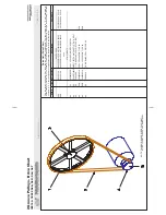
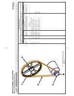
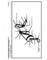
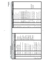
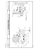
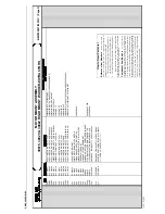
See the drive chart drawing (see Table of Contents) for part numbers and mechanical relationships among all
drive train components.
Ê
Cylinder Speeds
Machines covered by this section have four cylinder speeds. Slowest to fastest, these are wash, drain, low ex-
tract speed (E1), and high extract speed (E2).
Wash speed occurs during washing and rinsing bath steps. The cylinder reverses direction approximately twice
per minute as explained in “How the Machine Reverses” in this section.
Drain speed initiates water removal and distributes the goods evenly in the cylinder for efficient extraction.
Drain speed ranges from 69 to 81 RPMs, depending on the model.
Low extract speed ranges from 183 to 250 RPMs, depending on the model. Low extract speed occurs when an
extract precedes a wash, and before the machine accelerates to high extract speed.
High extract speed is used to extract the maximum possible moisture from the goods before the formula ends.
Range is 400 to 739 RPMs, depending on the model.
Ê
Drive Train Components and Operating Sequences
A microprocessor controller directs the machine through the required steps for each program. Controllers are
fully described elsewhere. Major drive train components include two motors (E1/wash and E2/drain), two clutches
(wash and extract), a jack shaft, and a system of V-belts and pulleys. To achieve various speeds, motors energize
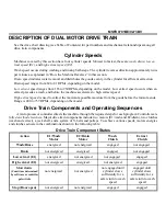
and clutches actuate in the combinations shown in the following table:
Ï
Drive Train Component States
Action
E1/Wash
Motor
E2/Drain
Motor
Wash
Clutch
Extract
Clutch
Wash/Rinse
energized
not energized
engaged
not engaged
Drain
not energized
energized
engaged
not engaged
Low extract (E1)
energized
not energized
not engaged
engaged
High extract (E2)
not energized
energized
not energized
engaged
Slow down
(Coast time determined
by software or centrifu-
gal switch)
not energized
not energized
not engaged until
cylinder slows
sufficiently for a
safe return to wash
speed
engaged until
cylinder slows
sufficiently for a
safe return to wash
speed
Stop (Door open)
not energized
not energized
engaged
engaged
Ë
Drive Train Precautions
Do not subject the drive train to stress by instantaneous transitions from stop or wash to extract speeds,
nor from extract to wash speeds. To avoid damaging the mechanical components and hazardous conditions, the
motors and clutches gradually accelerate and decelerate the cylinder. These gradual speed changes are inherent in
all control systems and must not be bypassed through manual operation or programming modifications.
Ë
How Clutches Work
NEVER LUBRICATE CLUTCHES!
☞
Lubrication prevents clutches from transmitting sufficient torque.
Wash and extract clutches operate on 12VDC from a clutch circuit described in this section. The wash clutch
is engaged whenever the clutch relay K0 is energized (wash or drain). The extract clutch is engaged whenever the
relay K0 is not energized (low and high extract). Clutches have two major parts, a stationary coil (bolted to the motor
frame), and a rotating pulley assembly (bolted to motor shaft). Clutches are magnetically actuated and have metal
faces without friction material. Clutches are not serviceable.
Ë
The Clutch Circuit
The clutch circuit uses transformers and rectifiers to convert alternating current control circuit voltage to direct
current for clutches. Service voltage is first converted to control circuit voltage (240VAC for most models, 120
VAC for M4P, M5P, M6P, and M7P models). This voltage is fed to the clutch circuit transformer, where it is
converted to 16.5VAC, then delivered to the clutch rectifiers. There is one rectifier for each clutch, providing
12VDC. Fuses protect all components. Rectifiers and transformers are extremely reliable, and require no mainte-
nance. However, because rectifiers are sensitive to excessive voltage, in the unlikely event of burned fuses, check
for component damage before returning the machine to service. As a safety feature, the clutch circuit also prevents
cylinder rotation with the door open. Both clutches engage, locking the jackshaft when the door is open and power
is supplied to the machine.
Ë
Malfunctioning Clutches or Clutch Circuits
The low speed (wash speed) drive train is disengaged during extract. At the end of extract, the extractor is
designed to slow down before the low speed drive train engages. Although extremely unlikely in a properly
maintained machine, a malfunction could cause the low speed drive to engage prematurely (a possibility
common to all types of industrial machines which have both a high speed and low speed operating cycle).
Summary of Contents for 30015
Page 6: ......
Page 8: ......
Page 10: ......
Page 19: ...Section 1 Service and Maintenance ...
Page 51: ...Section 2 Drive Assemblies ...
Page 59: ...BMP950003 95107V Page 1 MOTOR MOUNT 30015 30020 S4A S4G S4J S4T ...
Page 68: ......
Page 69: ...Section 3 Bearing Assemblies ...
Page 72: ...BMP910032 96141V Page 1 MAIN BEARING ASSEMBLY 30015C4x M4x K5x S5x ...
Page 74: ...BMP910033 96141V Page 1 MAIN BEARING ASSEMBLY ...
Page 76: ...BMP910034 95116V Page 1 MAIN BEARING ASSEMBLY 30015M6x ...
Page 80: ...BMP910035 93251V Page 1 JACKSHAFT ASSEMBLY 30015 30020 30022 RIGID MOUNT WASHER EXTRACTORS ...
Page 82: ......
Page 83: ...Section 4 Shell and Door Assemblies ...
Page 86: ...BMP920009 94491V Page 1 DOOR ASSEMBLY 30015 30020 RIGID MOUNT WASHER EXTRACTORS ...
Page 90: ......
Page 91: ...Section 5 Control and Sensing Devices ...
Page 100: ...BMP920010 97281V Page 1 COIN ASSEMBLY INSTALLATION 240V 30015 30020 30022 COIN MACHINES ...
Page 105: ...Section 6 Chemical Supply Devices ...
Page 113: ...Section 7 Water and Steam Piping and Assemblies ...
Page 114: ...ISOMETRIC SYMBOLS STANDARD SYMBOLS BMP920008 93027V Page 1 SCHEMATIC SYMBOLS KEY ...
Page 132: ...BMP920021 93251V Page 1 STEAM INSTALLATION 30015 30020 30022 RIGID MOUNT WASHER EXTRACTORS ...
Page 138: ...BMP920017 93251V Page 1 ELECTRIC DRAIN VALVE 30015 30020 30022 RIGID MOUNT WASHER EXTRACTORS ...

