MSSM0706BE/9273DV
È
DRIVE TRAIN SERVICE FOR ALL 30015 AND 30022
RIGID MOUNT WASHER-EXTRACTORS
Provide part number, model and serial number of the machine when ordering replacement parts from Milnor
®
.
Part numbers for clutches, belts, and pulleys are located on the machine drive chart drawings (if provided), see the
Table of Contents. When ordering motors, provide the motor nameplate description. Clutches should be purchased
from Milnor
®
to ensure optimum performance and service life.
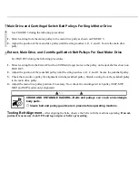
ENTANGLE AND CRUSH HAZARD—Belts and pulleys can entangle and crush
body parts.
☞
Lock OFF and tag out power at the wall disconnect before servicing.
Ê
Replacing Belts
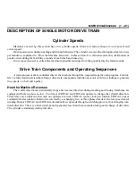
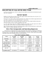
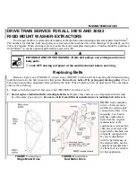
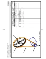
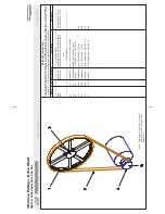
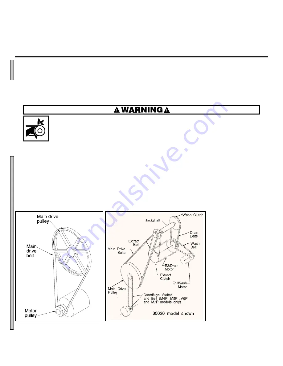
Remove single motor (FIGURE 1) or dual motor (FIGURE 2) drive belts by loosening the threaded jacking
rods that determine the belt tension for that pulley. Do not force belts off by prying and turning pulley. Check
belt tension and pulley alignment after replacing the belts. When replacing belts on dual motor drive machines,
observe the following:
1. Replace both the drain belt and extract belt (FIGURE 2) if either is worn.
2. Do not replace individual belts of multiple-belt sets. Replace these belts as a set. Replacement belts must
be of the same type and style. Do not use belts from different manufacturers in multiple-belt drive sets.
NOTE: Some manufac-
turer’s v-belts are more
suitable for certain appli-
cations than others. Con-
sequently, it is best to
purchase replacement
belts from the original
manufacturer of the
equipment, or at least pur-
chase the exact style and
type belt the machine was
originally equipped with.
If you are dissatisfied
with the performance of
the original belts, ask the
equipment manuafacturer
if a better belt is available
for that application.
Ê
Testing Belt Tension
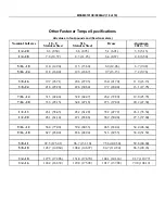
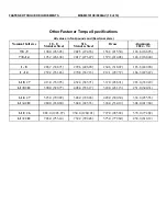
NOTE: Use the “Initial Tension” column (Table A
or B below) when adjusting belts that have never
been used. Use the “Final Tension” column when
adjusting belts that have been used.
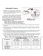
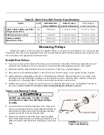
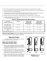
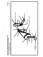
Check belt tension (FIGURE 3) when replacing
and adjusting drive train components. Belt tension test-
ing tool (Milnor
®
part number 30T001), straight edge,
and Belt Tension Tables are required when setting belt
tensions. Do not refer to instruction sheet provided
with tension testing tool. Check tensions for new belts
according to the following schedule:
•
After 24 hours of operation (three eight-hour days)
•
After 80 hours of operation (ten eight-hour days)
•
After 160 hours of operation (twenty eight-hour days)
1. Move upper O-ring on the tension testing tool to the uppermost position (resting against the bottom edge of
sliding cap).
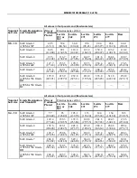
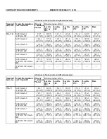
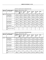
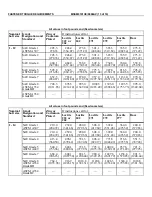
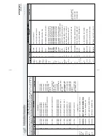
2. Determine deflection for the tested belt (see FIGURES 1 and 2 for the belt location and Tables A and B for
the setting range). Move lower O-ring to the correct setting (inches or centimeters) on scale. Read the bot-
tom edge of the O-ring.
3. Place a straight edge along the top edge (pulley to pulley) of the belt to be tested (FIGURES 1 and 2). Depress
the tension testing tool by sliding the cap against the middle of the belt span until the bottom edge of the
lower O-ring aligns with the straight edge as shown in FIGURE 3.
4. Read the top edge of the upper O-ring position and determine if it is within the specified range. If the readings
are below the specified range, tighten the belt. If the readings are above the specified range, loosen the belt.
Adjust the belt and repeat steps one through four until tension is within the specified range.
Ï
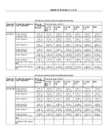
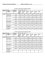
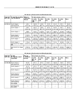
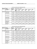
Table A—Belt Tension Specifications—All Belts on Dual Motor Machines
Except Main Drive Belts
Belt Application
Belt Deflection
inches (millimeters)
Initial Tension
pounds (kilograms)
Final Tension
pounds (kilograms)
Wash
3/16
(4.76)
5.1-6.6 (2.5-3.0)
3.9-5.1 (1.7-2.5)
Drain
5/32
(3.97)
3.7-4.9 (1.6-2.1)
2.9-3.8 (1.0-1.7)
Extract
5/32
(3.97)
5.1-6.6 (2.5-3.0)
3.9-5.1 (1.7-2.5)
Centrifugal switch
(M4P,M5P,M6P,
and M7P only)
17/64 (6.75)
3.6
(1.5)
3.1
(1.1)
Î
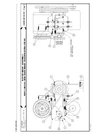
FIGURE 1
(MSSM0706BE)
Î
Single Motor Drive
Î
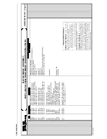
FIGURE 2
(MSSM0706BE)
Î
Dual Motor Drive
Î
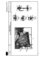
FIGURE 3
(MSSM0706BE)
Î
Testing Belt Tension
C
B
C
D
C
D
Summary of Contents for 30015
Page 6: ......
Page 8: ......
Page 10: ......
Page 19: ...Section 1 Service and Maintenance ...
Page 51: ...Section 2 Drive Assemblies ...
Page 59: ...BMP950003 95107V Page 1 MOTOR MOUNT 30015 30020 S4A S4G S4J S4T ...
Page 68: ......
Page 69: ...Section 3 Bearing Assemblies ...
Page 72: ...BMP910032 96141V Page 1 MAIN BEARING ASSEMBLY 30015C4x M4x K5x S5x ...
Page 74: ...BMP910033 96141V Page 1 MAIN BEARING ASSEMBLY ...
Page 76: ...BMP910034 95116V Page 1 MAIN BEARING ASSEMBLY 30015M6x ...
Page 80: ...BMP910035 93251V Page 1 JACKSHAFT ASSEMBLY 30015 30020 30022 RIGID MOUNT WASHER EXTRACTORS ...
Page 82: ......
Page 83: ...Section 4 Shell and Door Assemblies ...
Page 86: ...BMP920009 94491V Page 1 DOOR ASSEMBLY 30015 30020 RIGID MOUNT WASHER EXTRACTORS ...
Page 90: ......
Page 91: ...Section 5 Control and Sensing Devices ...
Page 100: ...BMP920010 97281V Page 1 COIN ASSEMBLY INSTALLATION 240V 30015 30020 30022 COIN MACHINES ...
Page 105: ...Section 6 Chemical Supply Devices ...
Page 113: ...Section 7 Water and Steam Piping and Assemblies ...
Page 114: ...ISOMETRIC SYMBOLS STANDARD SYMBOLS BMP920008 93027V Page 1 SCHEMATIC SYMBOLS KEY ...
Page 132: ...BMP920021 93251V Page 1 STEAM INSTALLATION 30015 30020 30022 RIGID MOUNT WASHER EXTRACTORS ...
Page 138: ...BMP920017 93251V Page 1 ELECTRIC DRAIN VALVE 30015 30020 30022 RIGID MOUNT WASHER EXTRACTORS ...

