background image

BMP

92

00

27

/93

2

5

1

V

(P

a

ge

 1)

M

O

TOR MOUNT ASSEMBLY

30015, 

30020 & 

30022 RIGID MOUNT WASHER-EXTRACTORS

DRIV

E

 AS

SE

MBL

IE

S

Summary of Contents for 30015

Page 1: ...ECN MAP30RM1AE 99033N Publishing System TPAS Access date 05 11 2000 Document ECN s Latest Available Service 30015 30020 30022 Washer Extractors PELLERIN MILNOR CORPORATION POST OFFICE BOX 400 KENNER LOUISIANA 70063 0400 U S A ...

Page 2: ...cluding the publishing system access date and whether the document ECN s are the latest available or exact References to Yellow Troubleshooting Pages This manual may contain references to yellow pages Although the pages containing troubleshooting procedures are no longer printed on yellow paper troubleshooting instructions if any will be contained in the easily located Troubleshooting chapter or s...

Page 3: ... Groove Pulleys Drive Chart 30015 30022 S4A S4G S4J S4T BMP970086 98383V 48 Drive Chart Rigid Mount Washer Extractors 30015M4J M4G M4T M6J M6G 30022M5J M5G M5T BMP910031 98373V 51 Motor Mount Assembly 30015 30020 30022 Rigid Mount Washer Extractors BMP920027 93251V 53 Motor Mount 30015 30020 S4A S4G S4J S4T BMP950003 95107V 55 Replacing Main Bearings and Seals on 30015 30020 30022Cxx Kxx Sxx and M...

Page 4: ...gid Mount Washer Extractors BMP920013 93251V 107 Section 7 Water and Steam Piping and Assemblies 108 Schematic Symbols Key BMP920008 93027V 109 Water Steam Drain Schematics 30015 30020 30022 Rigid Mount Washer Extractors BMP920015 96132V 111 Water Inlet Level Switch Installation Mounting Hardware 30015 30020 30022 Rigid Mount Washer Extractors BMP920016 93251V 113 Hays Electric Inlet Valves BMP700...

Page 5: ...ents cont Page Description Document ECN 133 Section 8 Pneumatic Piping and Assemblies 134 Pneumatic Schematic 30015 30020 30022 Rigid Mount Washer Extractors BMP920018 93251V 135 3 Way Pilot Valves BMP900032 91182V ...

Page 6: ......

Page 7: ...mber date code is located on the inside front cover upper right corner just above the manual name Whenever the manual is reprinted with new information part of this number changes If the date code after the changes the new version applies to all machines covered by the old version but is improved thus the old version can be discarded If the manual number before the changes the new manual covers on...

Page 8: ......

Page 9: ...points brake and clutch linings and similar parts are not covered by this warranty nor are parts damaged by exposure to weather or to chemicals We reserve the right to make changes in the design and or construction of our equipment including purchased components without obligation to change any equipment previously supplied ANY SALE OR FURNISHING OF ANY EQUIPMENT BY MILNOR IS MADE ONLY UPON THE EX...

Page 10: ......

Page 11: ...6 In correspondence regarding motors or electrical controls please include all nameplate data including wiring diagram number and the make or manufacturer of the motor or controls All parts will be shipped C O D transportation charges collect only Please read this manual It is strongly recommended that you read the installation and operating manual before attempting to install or operate your mach...

Page 12: ...peration For washer extractors see ABOUT THE FORCES TRANSMITTED BY MIL NOR WASHER EXTRACTORS Provide sufficient clearance for machine movement Provide any safety guards fences restraints devices and verbal and or posted restrictions necessary to prevent personnel machines or other moving machinery from accessing the machine or its path Provide adequate ventilation to carry away heat and vapors Ens...

Page 13: ...achine control panels disable only control circuit power in certain boxes You can be killed or seri ously injured on contact with high voltage Lock OFF and tag out power at the wall disconnect before servicing except where specifically instructed otherwise in this manual ENTANGLE AND CRUSH HAZARD Belts and pulleys can entangle and crush body parts Lock OFF and tag out power at the wall disconnect ...

Page 14: ... hand inching Any evidence of cylinder damage Missing or removed guards covers or side panels Malfunctioning tilting components including but not limited to safety limit switches electrical interlocks and operator controls If any of these conditions occur The machine makes a sound like skidding automobile tires as it comes out of extract The wash or drain clutch does not disengage or it reengages ...

Page 15: ...e instructions before continuing Do not jack the machine here Do not lift the machine here Use three point or four point lifting as determined by the lifting eyes furnished Rig the load using lifting cables of sufficient size and length to ensure cables are not over stressed Do not lift the machine from one corner or one side edge ...

Page 16: ...removed These materials are painted red Safety stands or brackets also painted red may be provided with this machine Do not discard safety stands or brackets This motor or pump should rotate in the direction of the arrow Do not start this machine until the part with this tag is installed on the machine Do not remove this component from the machine ...

Page 17: ...xplanation Install the appropriate part here before operating the machine During drain and extract the cylinder must rotate counterclockwise when viewed from here 7 _ccQbi _V DQW 9 ecdbQdY_ c Cdi U GQcXUb 5hdbQSd_bc ...

Page 18: ...Illustration Explanation Do not strike shell front of washer extractors during fork lifting Striking shell front will cause door to leak This is the hot water inlet C9EE D715 3F ...

Page 19: ...Section 1 Service and Maintenance ...

Page 20: ... see NOTE 1 Drive train Check belt tension and wear Check pulleys and other drive components for wear Replace if necessary every four months MSSM0706BE see NOTE 1 3 5 Compartment Supply injector if so equipped Inspect and clean strainers in water valves and each compartment If rust is detected carefully clean it away once each week every four months BMP770149 BMP920019 see NOTE 2 Steam strainer if...

Page 21: ... off drained oil and magnetic drain plug for water and or metal particles Water and or metal particles can indicate worn or damaged seals and bearings See REPLACING MAIN BEAR INGS AND SEALS if provided see Table of Contents Install the drain plug 3 Locate the two 1 2 plastic tubes secured to the frame Clean the surrounding area and remove the cork stoppers from each MALFUNCTION HAZARD Oil spilled ...

Page 22: ...using Any high quality SAE 30 40 or 50 ISO 100 140 or 220 single weight heavy duty motor oil non detergent if available 22 ounces 623 7 grams Ë Bolt Inspection Check the main bearing support bolts for tightness as shown in FIGURE 1 Î FIGURE 1 MSSM0705CE Î Main Bearing Housing Bolt Locations ...

Page 23: ... data Actual allowable torques are application dependent and can vary for many reasons joint types gaskets etc Use these values as a guide 5 Although FIGURE 1 depicts hex head bolts the table applies to all head types Ê Fasteners and Threadlocker Ë How Fasteners Loosen Standard threaded fasteners are manufactured with a clearance fit for easy assem bly With the fastener at the proper torque 85 of ...

Page 24: ...rimer N Allow to dry 3 Insert bolt into through hole assembly 4 Apply several drops of threadlocker onto bolt engage ment area 5 Assemble and tighten nut to correct torque for the threadlocker Ë Blind Holes See FIGURE 4 1 Clean all threads bolt and nut with cleaning solvent 2 Spray all threads with Loctite Primer N Allow to dry 3 Squirt several drops down female threads into bottom of hole 4 Apply...

Page 25: ...octite 277 Bare 1 4 20 SAE Grade 1 ASTM A307 2 5 3 39 3 0 4 06 3 3 4 47 3 6 4 88 4 6 6 23 4 3 5 83 3 3 4 47 SAE Grade 2 4 1 5 56 4 9 6 64 5 5 7 45 6 0 8 13 7 7 10 44 7 1 9 63 5 5 7 46 SAE Grade 4 4 8 6 50 5 8 7 86 6 4 8 67 7 0 9 49 9 0 12 20 8 3 11 25 6 4 8 67 SAE Grade 5 ASTM A449 6 3 8 54 7 6 10 3 8 4 11 38 9 3 12 60 11 8 15 99 11 0 14 91 8 4 11 39 SAE Grade 7 7 9 10 7 9 4 12 7 10 5 14 23 11 5 1...

Page 26: ...3 99 13 6 18 44 ASTM A354 Grade BC Ï All values in foot pounds and Newton meters Nominal bolt size Grade Designation and Standard Zinc or Cadmium Plated If instructions call for Loctite 222 or262 Loctite 242 Loctite 271 Loctite 272 Loctite 277 Bare 5 16 18 SAE Grade 1 ASTM A307 5 1 6 91 6 2 8 40 6 8 9 22 7 5 10 17 9 6 13 02 8 9 12 07 6 8 9 22 SAE Grade 2 8 5 11 52 10 2 13 83 11 3 15 32 12 5 16 95 ...

Page 27: ... 27 1 36 74 ASTM A354 Grade BC Ï All values in foot pounds and Newton meters Nominal bolt size Grade Designation and Standard Zinc or Cadmium Plated If instructions call for Loctite 222 or 262 Loctite 242 Loctite 271 Loctite 272 Loctite 277 Bare 3 8 16 SAE Grade 1 ASTM A307 9 0 12 20 10 8 14 64 12 0 16 27 13 1 17 76 16 7 22 64 15 5 21 01 12 0 16 27 SAE Grade 2 14 9 20 20 17 9 24 27 19 9 26 98 21 9...

Page 28: ... 41 64 0 86 77 49 2 66 70 ASTM A354 Grade BC Ï All values in foot pounds and Newton meters Nominal bolt size Grade Designation and Standard Zinc or Cadmium Plated If instructions call for Loctite 222 or 262 Loctite 242 Loctite 271 Loctite 272 Loctite 277 Bare 7 16 14 SAE Grade 1 ASTM A307 14 0 18 98 17 0 23 04 19 14 25 95 21 0 28 47 27 0 36 60 25 0 33 89 19 0 25 76 SAE Grade 2 24 0 32 54 28 8 39 0...

Page 29: ... 35 ASTM A354 Grade BC Ï All values in foot pounds and Newton meters Nominal bolt size Grade Designation and Standard Zinc or Cadmium Plated If instructions call for Loctite 222 or262 Loctite 242 Loctite 271 Loctite 272 Loctite 277 Bare 1 2 13 SAE Grade 1 ASTM A307 22 0 29 83 26 0 35 25 29 38 39 83 32 0 43 39 41 0 55 59 38 0 51 52 29 0 39 32 SAE Grade 2 36 6 49 62 43 9 59 52 48 8 66 16 53 6 72 67 ...

Page 30: ...51 120 0 162 70 ASTM A354 Grade BC Ï All values in foot pounds and Newton meters Nominal bolt size Grade Designation and Standard Zinc or Cadmium Plated If instructions call for Loctite 222 or 262 Loctite 242 Loctite 271 Loctite 272 Loctite 277 Bare 9 16 12 SAE Grade 1 ASTM A307 32 0 43 39 38 0 51 52 42 19 57 20 46 0 62 37 59 0 80 00 55 0 74 57 42 56 94 SAE Grade 2 52 7 71 45 63 3 85 82 70 3 95 31...

Page 31: ...1 6 232 66 ASTM A354 Grade BC Ï All values in foot pounds and Newton meters Nominal bolt size Grade Designation and Standard Zinc or Cadmium Plated If instructions call for Loctite 222 or 262 Loctite 242 Loctite 271 Loctite 272 Loctite 277 Bare 5 8 11 SAE Grade 1 ASTM A307 44 59 66 52 70 50 58 2 78 90 64 86 77 81 109 82 76 103 04 58 78 64 SAE Grade 2 72 7 98 57 87 2 118 23 96 9 131 38 106 6 144 53...

Page 32: ... 8 422 74 239 8 325 13 ASTM A354 Grade BC Ï All values in foot pounds and Newton meters Nominal bolt size Grade Designation and Standard Zinc or Cadmium Plated If instructions call for Loctite 222 or 262 Loctite 242 Loctite 271 Loctite 272 Loctite 277 Bare 3 4 10 SAE Grade 1 ASTM A307 77 104 40 93 126 09 103 1 139 78 113 153 20 144 195 24 134 181 68 103 139 65 SAE Grade 2 129 4 175 44 155 3 210 55...

Page 33: ...569 44 ASTM A354 Grade BC Ï All values in foot pounds and Newton meters Nominal bolt size Grade Designation and Standard Zinc or Cadmium Plated If instructions call for Loctite 222 or 262 Loctite 242 Loctite 271 Loctite 272 Loctite 277 Bare 7 8 9 SAE Grade 1 ASTM A307 124 7 169 07 149 6 202 83 166 3 225 47 182 9 247 98 232 8 315 63 216 1 293 0 166 3 225 47 SAE Grade 2 124 7 169 07 149 6 202 83 166...

Page 34: ...4 668 3 906 09 ASTM A354 Grade BC Ï All values in foot pounds and Newton meters Nominal bolt size Grade Designation and Standard Zinc or Cadmium Plated If instructions call for Loctite 222 or 262 Loctite 242 Loctite 271 Loctite 272 Loctite 277 Bare 1 8 SAE Grade 1 ASTM A307 187 5 254 22 225 0 305 06 250 0 338 95 275 0 372 85 350 0 474 54 325 0 440 64 250 0 338 95 SAE Grade 2 187 5 254 22 225 0 305...

Page 35: ... 1483 49 1393 0 1888 66 1293 5 1753 73 995 0 1349 04 ASTM A354 Grade BC Ï All values in foot pounds and Newton meters Nominal bolt size Grade Designation and Standard Zinc or Cadmium Plated If instructions call for Loctite 222 or 262 Loctite 242 Loctite 271 Loctite 272 Loctite 277 Bare 1 14 SAE Grade 1 ASTM A307 210 0 284 72 252 0 341 66 280 0 379 63 308 0 417 60 392 0 531 48 364 0 493 52 280 0 37...

Page 36: ...88 1 1746 43 ASTM A354 Grade BC 844 8 1145 40 1013 8 1374 53 1126 4 1527 20 1239 0 1679 86 1577 0 2138 13 1464 3 1985 33 1126 4 1527 20 Ï All values in foot pounds and Newton meters Nominal bolt size Grade Designation and Standard Zinc or Cadmium Plated If instructions call for Loctite 222 or 262 Loctite 242 Loctite 271 Loctite 272 Loctite 277 Bare 1 1 8 12 SAE Grade 1 ASTM A307 297 4 403 22 356 9...

Page 37: ...STM A354 Grade BC 1192 4 1616 68 1430 9 1940 04 1589 8 2155 48 1748 8 2371 05 2225 8 3017 78 2066 8 2802 20 1589 8 2155 48 Ï All values in foot pounds and Newton meters Nominal bolt size Grade Designation and Standard Zinc or Cadmium Plated If instructions call for Loctite 222 or 262 Loctite 242 Loctite 271 Loctite 272 Loctite 277 Bare 1 1 4 12 SAE Grade 1 ASTM A307 414 8 562 40 497 8 674 93 553 1...

Page 38: ... 2 3229 83 ASTM A354 Grade BC 1563 6 2119 96 1876 4 2544 06 2084 8 2826 61 2293 3 3109 30 2918 8 3957 37 2710 3 3674 68 2084 8 2826 61 Ï All values in foot pounds and Newton meters Nominal bolt size Grade Designation and Standard Zinc or Cadmium Plated If instructions call for Loctite 222 or 262 Loctite 242 Loctite 271 Loctite 272 Loctite 277 Bare 1 3 8 12 SAE Grade 1 ASTM A307 559 5 758 58 671 3 ...

Page 39: ...ASTM A354 Grade BC 2074 9 2813 20 2489 9 3375 85 2766 6 3751 01 3043 2 4126 03 3873 2 5251 36 3596 5 4876 20 2766 6 3751 01 Ï All values in foot pounds and Newton meters Nominal bolt size Grade Designation and Standard Zinc or Cadmium Plated If instructions call for Loctite 222 or 262 Loctite 242 Loctite 271 Loctite 272 Loctite 277 Bare 1 1 2 12 SAE Grade 1 ASTM A307 734 1 995 30 880 9 1194 34 978...

Page 40: ...24 21 6 29 28 22 6 30 64 17 7 24 00 13 1 17 76 7 16 14 31 3 42 44 32 8 44 47 26 4 35 80 19 0 25 76 7 16 20 33 3 45 15 34 8 47 18 27 3 37 00 20 2 27 38 1 2 13 43 1 58 43 45 2 61 28 35 2 47 72 26 1 35 38 1 2 20 45 1 61 14 47 1 63 86 36 9 50 00 27 3 37 00 9 16 12 56 8 77 00 59 4 80 53 46 5 63 04 34 4 46 64 9 16 18 62 7 85 00 65 6 88 94 51 3 69 55 38 0 51 52 5 8 11 92 5 125 41 96 7 131 10 75 6 102 50 ...

Page 41: ...06 20 234 6 318 07 183 8 249 20 1 14 259 2 351 43 270 8 367 16 212 1 287 57 166 3 225 47 1 1 8 7 413 0 559 95 432 0 585 71 337 0 456 91 265 0 359 29 1 1 8 12 390 0 528 77 408 0 553 17 318 0 431 15 251 0 340 31 1 1 4 7 523 0 709 09 546 0 740 28 428 0 580 30 336 0 455 55 1 1 4 12 480 0 650 80 504 0 683 33 394 0 534 19 308 0 417 60 1 1 2 6 888 0 1203 97 930 0 1260 91 727 0 985 68 570 0 772 82 1 1 2 1...

Page 42: ...gh the required steps for each program Control lers are fully described elsewhere Major drive train components include one motor with two windings to generate two speeds a v belt and a pulley Ë How the Machine Reverses The wash extract motor periodically stops and reverses direction during washing and rinsing Machines are equipped with three phase motors Two relays CRWAC and CRWAA operate to chang...

Page 43: ...om the goods before the formula ends Range is 400 to 739 RPMs depending on the model Ê Drive Train Components and Operating Sequences A microprocessor controller directs the machine through the required steps for each program Controllers are fully described elsewhere Major drive train components include two motors E1 wash and E2 drain two clutches wash and extract a jack shaft and a system of V be...

Page 44: ...ectifiers to convert alternating current control circuit voltage to direct current for clutches Service voltage is first converted to control circuit voltage 240VAC for most models 120 VAC for M4P M5P M6P and M7P models This voltage is fed to the clutch circuit transformer where it is converted to 16 5VAC then delivered to the clutch rectifiers There is one rectifier for each clutch providing 12VD...

Page 45: ...ash clutch Ê How the Machine Reverses The wash E1 motor periodically stops and reverses direction during washing and rinsing Machines are equipped with either single phase or three phase motors each using a different method to reverse rotation Two relays CRWAC and CRWAA operate to change the cylinder direction These relays are actuated so that only one operates at a time CRWAC causes clockwise rot...

Page 46: ...force belts off by prying and turning pulley Check belt tension and pulley alignment after replacing the belts When replacing belts on dual motor drive machines observe the following 1 Replace both the drain belt and extract belt FIGURE 2 if either is worn 2 Do not replace individual belts of multiple belt sets Replace these belts as a set Replacement belts must be of the same type and style Do no...

Page 47: ...the correct setting inches or centimeters on scale Read the bot tom edge of the O ring 3 Place a straight edge along the top edge pulley to pulley of the belt to be tested FIGURES 1 and 2 Depress the tension testing tool by sliding the cap against the middle of the belt span until the bottom edge of the lower O ring aligns with the straight edge as shown in FIGURE 3 4 Read the top edge of the uppe...

Page 48: ...ore are dry and free of dirt burrs and old adhesives 3 Place the key in the shaft and pulley to check key fit Key must fit snugly if not replace the key or pulley 4 Apply retaining compound Loctite 609 to the pulley bore and shaft being careful not to over apply Turn the pulley back and forth while installing to evenly distribute Loctite Align the pulley with the correspond ing pulley see Aligning...

Page 49: ...al motor drive 1 4 x 20 54 62 108 1 24 P1 30020 and 30022 Dual motor drive 5 16 x 18 96 1 10 190 2 18 SD All single motor drive 1 4 x 20 54 62 110 1 26 Ë Electric Clutch Pulleys Do not use a pulling tool to remove the clutch Remove the clutch by removing the center mounting bolt and gently tapping the clutch off Ê Aligning Pulleys After replacing the drive train components check the pulley alignme...

Page 50: ...haft as shown on FIGURE 5 2 Adjust the position of the jackshaft pulley until the string touches A B C and D Secure the jackshaft pulley 3 Check the main drive pulley for alignment with the jackshaft pulley Stretch a string from the jackshaft pulley to the main drive pulley 4 Adjust the main drive pulley position if necessary Now check the centrifugal switch pulley M4P M5P M6P and M7P models only ...

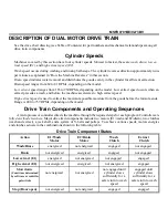
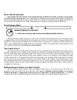
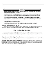
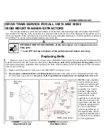
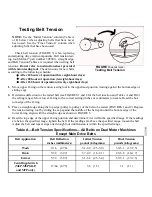
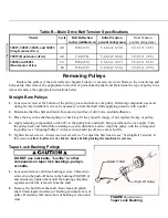
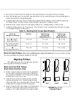
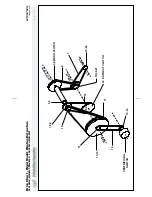
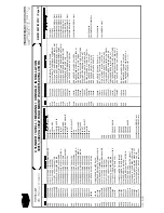
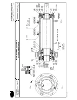
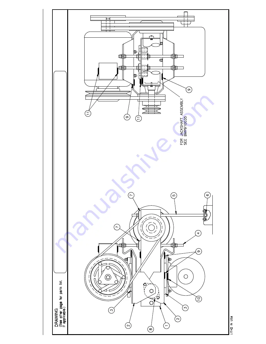
Page 51: ...Section 2 Drive Assemblies ...

Page 52: ...t 2 Groove Pulleys Drive Chart 30015 30022 S4A S4G S4J S4T BMP930015 98383V Sheet 1 of 1 ASSEMBLIES 00A D33 03150 94000Z DRIVE CHART 3015 22S4 50CYC 3015 22S4X 50 CYCLE 00B D33 03160 94000Z DRIVE CHART 3015 22S4 60CYC 3015 22S4X 60 CYCLE none COMPONENTS all 001 560205R2SD VPUL 2G3V20 5 SD MTO SPECIAL all 002 56VR0750M2 VBELT 3V750 MATCHSET 2 EA 1 BELT all 003 56Q1KSD 1 1 2 BUSHING VPUL QD TYPE SD ...

Page 53: ...ive Chart 30015 30022 S4A S4G S4J S4T BMP970086 98383V Sheet 1 of 1 ASSEMBLIES 00A D33 03150 94000Z DRIVE CHART 3015 22S4 50CYC 3015 22S4X 50 CYCLE 00B D33 03160 94000Z DRIVE CHART 3015 22S4 60CYC 3015 22S4X 60 CYCLE none COMPONENTS all 001 562240R3SF VPUL 3G3V22 4 SF MTO SPECIAL all 002 56VR080XB3 VBAND 3R3VX800 EA 1 BELT all 003 56Q1KSF 1 1 2 BUSH VPUL QD TYPE SF all 004A 560295R3SH VPUL 3G3V2 9...

Page 54: ...0 Litho in U S A BMP910031 98373V Sheet 1 of 3 Drive Chart Rigid Mount Washer Extractors 30015M4J M4G M4T M6J M6G 30022 M5J M5G M5T 11 12 13 14 15 16 17 18 EXTRACT CLUTCH 19 10 7 8 9 5 6 3 4 WASH CLUTCH 2 1 10 22 10 20 21 CENTRIFUGAL SWITCH E2 J A C K S H A F T D R A I N E 1 W A S H M A I N ...

Page 55: ...5G M5J AND 3022M5X M5G COMPONENTS A B C 1 56VA034X VBELT AX34 DAYCO RAWEDGE COG D L M G H 1 56VA037X VBELT AX37 DAYCO RAWEDGE COG E F 1 56VA035X VBELT AX35 DAYCO RAWEDGE COG A F L 2 56VA035X VBELT AX35 DAYCO RAWEDGE COG M J K N 2 56VA038X V BELT AX38 1 RAWEDGE COG P G H J 1 56VA038X V BELT AX38 1 RAWEDGE COG K N P G H J 3 02 03624 VPUL CLUTCH A2G8 5 K N P A F L 4 54H160A CLUTCH 12VDC MA 7 3 8A 2G ...

Page 56: ...12VDC MA 7 3 8A 2G G H N 19 56VA037X VBELT AX37 DAYCO RAWEDGE COG P J K 19 56VA038X V BELT AX38 1 RAWEDGE COG A L 19 56VA036X VBELT AX36 DAYCO RAWEDGE COG B M 19 56VA036S VBELT A36 C F 19 56VA0383 VBELT AX38 3 COGGED G H J 20 02 03622B VPUL 875BORE A2G2 4 A1G6 25 K N P A F L 20 02 03312A VPUL 875BORE A2G2 0 A1G5 00 M G H 21 15Q072 SOKSETSCR CUP1 4 20X1 4BLKALLE J N P A B G 22 56028A10R VPUL 1A2 8 ...

Page 57: ...BMP920027 93251V Page 1 MOTOR MOUNT ASSEMBLY 30015 30020 30022 RIGID MOUNT WASHER EXTRACTORS DRIVE ASSEMBLIES ...

Page 58: ...EINFORCED 40 D 00C 00E 00H 009 12P1APSB SNAPBUSH 75MHX 627 T 25HEYCO 2840 010 12P1ARSB SNAPBUSH 7 8MHX3 8 T 1 8 HEYCO 2110 011 12P1ARNB SHORTYBUSH 7 8MHX 75ID HEYCO 2850 END OF PARTS LIST How to Read Parts List Reference Item Numbers I t e m s 0 0 A 0 0 B 00C etc or 00X 00Y 00Z etc appearing at the top of some parts lists are for reference and provide 1 The part number for the entire assembly depi...

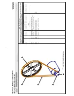
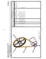
Page 59: ...BMP950003 95107V Page 1 MOTOR MOUNT 30015 30020 S4A S4G S4J S4T ...

Page 60: ...ts lists are for reference and provide 1 The part number for the entire assembly depicted in the drawing or a major sub assembly thereof and or 2 The range of machine models this drawing applies to If more than one reference item appears this usually means this drawing applies to more than one assembly and thus to more than one range of machines Component Item Numbers For any item on the drawing e...

Page 61: ...e Cylinder puller kit P N PK33 008 or equivalent available from Milnor on a rental or purchase basis Loctite 242 271 and 504 adhesives Dow Corning RTV 732 and Permatex 2 or equivalents Shell clamps Ê Removing the Shell Front and Cylinder Refer to CYLINDER SHELL BEARING CONSOLE INSTALLATION see Table of Contents and proceed as follows 1 Remove the door interlock housing cover Mark the terminal posi...

Page 62: ...mponents of the original bearing housing front shaft seal holder rear seal bearing holder shaft or shims are replaced See Setting Clearances in this section after replacing major components Often the bearing housing does not need to be removed to change the bearings Remove the shell and bearing housing only if insufficient space exists for the following procedures or if the bearing housing or hous...

Page 63: ...ring housing assembly or a major bearing housing component requires removal of the shell Ë Removing the Shell NOTE 1 30015 front bearing housing bolts are provided with self locking nuts NOTE 2 30020 and 30022 shell back clamp rings have three push off holes to aid in removal Replace the three plastic set screws with three bolts then tighten evenly to separate the ring from the shell 1 Clamp the s...

Page 64: ...ine On 30015 Machines Considerably loosen but do not fully remove the two rear bearing housing mounting bolts 1 Pry the bearing housing out of the console until the rear mounting bolts bottom out 2 Remove the rear mounting bolts one at a time and catch the shims with your fingers through the holes in the rear console member next to the bearing housing Note the position of the shims they must be re...

Page 65: ...front console with new clips 1 Determine that all threaded holes are clean and in good condi tion by screwing a new bolt into each hole if necessary tap out any damaged threads 2 Position the bearing housing in the console 3 Mount the gasket on the front of the bearing housing 4 Determine that the shell is clean and free from any old gasket material then mount the shell onto the console using new ...

Page 66: ...nsole 4 Mount the gasket and ring to the inside of the shell 5 Using Loctite 504 install the front bearing housing bolts and lockstraps through the ring and the bearing housing Tighten the bolts and bend the lockstraps as applicable 6 Pre position the two bearing support tap strips then install the rear reinforcing plate Install new alignment washers and original shims on rear mounting bolts FIGUR...

Page 67: ... can crack stainless steel components Do not use a metal hammer to seat the shell front or install the ring 5 Using clamps mount and support the shell front in place align it with the mark made before it was removed If necessary use a rubber or rawhide maul to strike the shell front so it seats within the shell After the shell front is seated properly on the shell check the gap between the shell f...

Page 68: ......

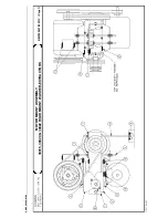
Page 69: ...Section 3 Bearing Assemblies ...

Page 70: ...BMP910037 93251V Page 1 CYLINDER SHELL BEARING CONSOLE INSTALLATION 30015 30020 30022 RIGID MOUNT WASHER EXTRACTORS ...

Page 71: ...ED 3020M7 PART OF 005D 008 Y2 02059 70256A SHELL CLAMP RING 30 MACHINE 009 02 02087C EXTRUS ION SHELL 30 MACHINES 8 5FT 010 02 03629 70238A LOCKSTRAP BEAR HOUS S S 30020 30022 MODELS ONLY 011 X2 03576 87326C RING SHELL BACK CLAMP 1 C6M 30020 30022 MODELS ONLY 012 02 03444 79381M RING SHELL BACK CLAMP 30015 ONLY 013A 02 03446 93123A1 GASKET SHELBACK CLAMPRING 30015 ONLY 013B 02 03575 93123A GASKET ...

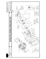
Page 72: ...BMP910032 96141V Page 1 MAIN BEARING ASSEMBLY 30015C4x M4x K5x S5x ...

Page 73: ...3323B 94387 SHIM 010 CRS RED AS REQUIRED 023D 02 03323C 94387 SHIM 0075 CRS BLACK AS REQUIRED 024 5SP0EFFSSM NPT PLUG 1 4 SQSLDMAGNET BLKST 025 5N0E01KBE2 NPT NIPPLE 1 4X1 5 TBE BRASS 125 026 5SCC0EBE NPT COUP 1 4 BRASS 125 103 027 X2 03436 94147D HOUSING MAIN BEARING 1 CWU 028 5N0E05AG42 NPT NIPPLE 1 4X5 TBE GALSTL SK40 029 02 03564 BOLTLOKTAB 030 15B080 HEXCAPSCR 5 16 X1 1 4 SS 18 8 031 X2 03437...

Page 74: ...BMP910033 96141V Page 1 MAIN BEARING ASSEMBLY ...

Page 75: ...03407 LOCKINGWASHER CADSTL 017 15K127 01Z HEXFLGSCR 3 8 16X2 GR8 CS 018 X2 03659A 93352B HOUSE SEAL BRG 30M V7 019 24S048AAA 04Z SEAL 1 625X2 375X 375 CS BUNA 020 X2 13103A 92236C SHAFT MAIN FOR 3020C5M N4M 021 54A308 M802048 TIMKEN 20024 1 BX MARK PT 022 54A307 CUP M802011 TIMKEN 2 24 1 BX PT 023A 02 03323 94387B SHIM 003 CRS GREEN AS REQUIRED 023B 02 03323A 94387 SHIM 005 CRS BLUE AS REQUIRED 02...

Page 76: ...BMP910034 95116V Page 1 MAIN BEARING ASSEMBLY 30015M6x ...

Page 77: ...6 02 03407 LOCKINGWASHER CADSTL 017 15K127 01Z HEXFLGSCR 3 8 16X2 GR8 CS 018 X2 03659A 93352B HOUSE SEAL BRG 30M V7 019 24S048AAA 04Z SEAL 1 625X2 375X 375 CS BUNA 020 X2 03314A 90147C MAIN SHAFT 3015N6E C6M 021 54A308 M802048 TIMKEN 20024 1 BX MARK PT 022 54A307 CUP M802011 TIMKEN 2 24 1 BX PT 023A 02 03320B 93353A SHIM 003 ARTUS GREEN 023B 02 03320C 93353 SHIM 005 ARTUS BLUE 023C 02 03320D 93353...

Page 78: ...the belts from the jackshaft Remove the straight bore pulley electric clutch and coil from the jackshaft for further information see DRIVE TRAIN SERVICE in the Table of Contents 3 Remove the four jackshaft mounting screws Ê Replacing the Bearing NOTE Provide enough clearance around the bottom of the hous ing FIGURE 1 as the bearing will come out with the shaft 1 Remove and discard the shaft clip a...

Page 79: ...other new bearing onto the shaft and place the shaft in side the housing with the tapered end into the installed bearing Place the assembly under the press with the housing completely supported by the inner and outer race of the bearing as shown in FIGURE 2 Simultaneously press the bearing onto the shaft and into the housing until the bearing bottoms out applying equal force to both inner and oute...

Page 80: ...BMP910035 93251V Page 1 JACKSHAFT ASSEMBLY 30015 30020 30022 RIGID MOUNT WASHER EXTRACTORS ...

Page 81: ... 00B 00C etc or 00X 00Y 00Z etc appearing at the top of some parts lists are for reference and provide 1 The part number for the entire assembly depicted in the drawing or a major sub assembly thereof and or 2 The range of machine models this drawing applies to If more than one reference item appears this usually means this drawing applies to more than one assembly and thus to more than one range ...

Page 82: ......

Page 83: ...Section 4 Shell and Door Assemblies ...

Page 84: ...BMP920024 93251V Page 1 SHELLFRONT ASSEMBLY CONDUIT INTERLOCK INSTALLATION 30015 30020 30022 RIGID MOUNT WASHER EXTRACTORS ...

Page 85: ...UT 1 4 20UNC2 SS18 8 END OF PARTS LIST How to Read Parts List Reference Item Numbers I t e m s 0 0 A 0 0 B 00C etc or 00X 00Y 00Z etc appearing at the top of some parts lists are for reference and provide 1 The part number for the entire assembly depicted in the drawing or a major sub assembly thereof and or 2 The range of machine models this drawing applies to If more than one reference item appe...

Page 86: ...BMP920009 94491V Page 1 DOOR ASSEMBLY 30015 30020 RIGID MOUNT WASHER EXTRACTORS ...

Page 87: ...M EC 1300 IN PINT CONT 024 15Q077 SOKSETSCR 1 4 20X1 4 ZINC ALLENONLY 025 03 01423C 86206B LATCH GUARD ILOC 3015 20 035 15U188 01Z FLTWASH 1 4 STD COMM SS18 8 036 15N191 FLATMACHSCR 1 4 20X7 8 SS18 8 U CUT 037 03 01420D 87487Y DOOR HANDLE ILOC 3015 20 END OF PARTS LIST How to Read Parts List Reference Item Numbers I t e m s 0 0 A 0 0 B 00C etc or 00X 00Y 00Z etc appearing at the top of some parts ...

Page 88: ...g lever is fully depressed with the door open 3 The arm does not over travel and hit the switch housing when the door is closed and the switch is actuated Bolt Spacer Adjustment 1 On a new machine the slots on the front housing should not show a gap past the bolt spacers 2 The spacers should be installed with the long side toward the shellfront SWITCH STRIKER ADJUSTMENT BOLT SPACER ADJUSTMENT ASSE...

Page 89: ...A 94186D HOUSING FRONT ILOC W UNLATC all 3 03 01427A 77181C HOUSING REAR ILOC C 7 D only 3 03 01427B 94186D HOUSING REAR ILOC W UNLATCH all 4 03 01429 75479C PLATE FNT PIVOT ILOC all 5 03 01335 INSULATOR AUTOSPOT all 6 03 01425A 92683C DOOR HANDLE EXTENSION all 7 03 01423 75736B LATCH INTERLOCK all 8 03 01417 75100B PLATE SPACER ILOC all 9 03 01418B 75194B KEEPER LATCH PIN NOTCH all 10 03 01418 75...

Page 90: ......

Page 91: ...Section 5 Control and Sensing Devices ...

Page 92: ...ly injured on contact with high voltage Lock OFF and tag out power at the wall disconnect before servicing Ë Replacing the Power Supply See FIGURE 1 during the following procedures 1 Remove the console top and belt guard 2 Remove the power supply and processor board covers 3 After replacing the power supply see Adjusting Output Voltage in this section Ë Adjusting Output Voltage CRUSH AND ENTANGLE ...

Page 93: ...tive meter probe to the rear of pin 3 5VDC Voltage must be between 4 95 and 5 06VDC If not turn the 5VDC potentiometer slowly clockwise to lower counterclockwise to raise until the meter displays the correct value The microprocessor will not operate if this voltage is not within tolerance After setting 5VDC output voltage with the negative meter probe still touching the rear of pin 9 ground connec...

Page 94: ... box dur ing the following procedure You can be killed or seriously injured by contact with exposed components which are energized at 120VAC or higher DO NOT touch any components while adjusting output voltage See FIGURES 3 and 4 during the following procedures NOTE 1 The 5VDC potentiometer power supplies prior to Mildate 92753 can be seen through the perforations in the metal case NOTE 2 On some ...

Page 95: ...t oper ate if this voltage is not within tolerance After setting 5VDC output voltage with the negative meter probe still touching pin 9 1 Touch the positive meter probe to pin 5 The voltage must be between 11 5 to 13 5VDC 2 Touch the positive meter probe to pin 7 The voltage must be between 11 5 to 13 5VDC Î FIGURE 4 MSSM0711AE Î Location of Output Voltage Potentiometer and Connector 1MTA31 After ...

Page 96: ...NOTE SEE ELECTRICAL SCHEMATIC MANUAL FOR ALL ELECTRICAL COMPONENTS BMP880028 96143V Page 1 SWITCH PANEL ASSEMBLY 30015 30020 30022 MxG MxJ Cxx K5x ...

Page 97: ...HLETIC 00U 003E 01 10442E 91393 GPX PNL SYS 7 SHIRT LAUNDRY 00V 003F 01 10442F 91393 GPX PNL SYS 7 COMMERCIAL 00W 003G 01 10442G 91393 GRAPHIC PNL OFFSHORE 00X 003H 01 10442J 91393 GPX PNL SYS 7 CORRECTIONAL 00Y 003I 01 10442K 91393 GRAPHIC PNL FAIRFIELD INN 00Z 004 03 E5X34 92356D ENCL SYSTEM 7 GRAPHIC PNLMTG 00Z 005A 03 BU413U 92356D BRKT M4 5 6J LCD FILTER EP10 00Q 005B 03 BU4X13 92356C BRKT SY...

Page 98: ...nd larger coins will not fit in the slot Four notches hold the coin rejector One notch se cures the coin rejector in place To release the coin rejec tor bend this notch slightly open with a screwdriver see FIGURE 1 Position the bent coin release lever as shown The coin rejector normally does not require any adjust ment but periodically wash the coin rejector in hot soapy water and remove metal fil...

Page 99: ...tempting align ment Note the minimum 1 64 inch 39 millimeter clearance between the inside coin slot arc and the actuator Set the coin switch to click OFF at least 1 16 inch 1 5 millimeter before the actuator reaches the top of the coin slot arc Bend the actuator slightly if necessary for proper adjustment To reposition the switch loosen both screws on the switch and move as necessary Avoid all thr...

Page 100: ...BMP920010 97281V Page 1 COIN ASSEMBLY INSTALLATION 240V 30015 30020 30022 COIN MACHINES ...

Page 101: ...NS ITEMS 19 20 018B 38C049A REJECTOR NEW CANADA 25J SEE SA33 68 OPT CANADIAN COIN REJECT 019 02 03302A 87211B INSERT CRANK SLIMLINE 020 02 03361 68020A CRANKWASHER CADPLATE 021 X2 03363 87262A COIN RETURN RECEPTACLE END OF PARTS LIST How to Read Parts List Reference Item Numbers I t e m s 0 0 A 0 0 B 00C etc or 00X 00Y 00Z etc appearing at the top of some parts lists are for reference and provide ...

Page 102: ...hine is set into position but before the machine is op erated Adjustment of this switch from the factory setting is not recommended however it should be checked for proper functioning and adjusted if its proper setting is lost As shown at right in FIGURE 1 the unit consists of a sensitive micro switch with an extended actuating arm sup porting an eccentric weight The weight may be adjusted by movi...

Page 103: ...ry substantial foundation very little machine movement will occur for a given degree of out of balance Under such conditions it may be better to adjust the switch to be very sensitive With less substantial foundations e g ones where the sub soil is mushy or springy or otherwise not as desirable considerably greater machine movement will occur for a given degree of out of balance in which case a le...

Page 104: ... provide 1 The part number for the entire assembly depicted in the drawing or a major sub assembly thereof and or 2 The range of machine models this drawing applies to If more than one reference item appears this usually means this drawing applies to more than one assembly and thus to more than one range of machines Component Item Numbers For any item on the drawing e g item there may be several c...

Page 105: ...Section 6 Chemical Supply Devices ...

Page 106: ...AMAGE THE WASHER EXTRACTOR 2 LOCATING CHEMICAL SYSTEM COMPONENTS TO REDUCE THE RISK OF INTERNAL DAMAGE 3 PREVENTING LEAKS WHICH CAN INJURE PERSONNEL AND CAUSE EXTERNAL DAMAGE SEE INSTRUCTION B2TAG86033 ON MACHINE BMP940077 94286V Page 1 LIQUID SUPPLY INLET SIDE MOUNT ...

Page 107: ...ntire assembly depicted in the drawing or a major sub assembly thereof and or 2 The range of machine models this drawing applies to If more than one reference item appears this usually means this drawing applies to more than one assembly and thus to more than one range of machines Component Item Numbers For any item on the drawing e g item there may be several corre sponding items on the parts lis...

Page 108: ...valve item 21 contains a strainer See PREVENTIVE MAINTENANCE in the Table of Contents for cleaning schedule BMP920019 93251V Page 1 SUPPLY INJECTOR AND INSTALLATION 30015 30020 30022 RIGID MOUNT WASHER EXTRACTORS ...

Page 109: ...471 87371B PLATE ADAPT TO 3 8 OR 1 2FIT 00A 00B 018 12K040 1 2 COND EMT CONDUIT PECO 260B 00A 00B 019 02 02730 75832A NIPPLE SUP INJ 215DEG 00D 020 02 02703 70089A NIPPLE SUPINJ 180DEG 00D 021 96P011A71 07Z 1 4 2 WAY 240V60 220V50 00D 022 SA 14 039 75627B PRESSGAGE FLUSHSUP 30 36 00E 023 96J030D 1 2 PRESREGULTR SET 28 FEM UNION 00E END OF PARTS LIST How to Read Parts List Reference Item Numbers I ...

Page 110: ...Corporation Pellerin Milnor Corporation P O Box 400 Kenner LA 70063 0400 Litho in U S A BMP770149 96113V Sheet 1 of 2 3 Compartment Supply Injector 30015 30020 30022 Rigid Mount Washer Extractors BMP770149 96113V 1 of 2 ...

Page 111: ...OMPONENTS all 1 02 03732B 94031B COVER 4 COMP SUPPLY VALVES all 2 02 03732F 90346C TAPPED PLATE SUPPLY MOUNT all 3 02 03304A 94493C GASKET SOAP CHUTE 1 8 EPDM all 4 W2 03732 93102D SUPPLY INJECTOR 4 COMP SUPP all 5 02 03732G 87501C LID 4 COMPARTMENT SUPPLY all 6 02 03732U 78302B GASKET LID 4 COMP SUPPLY all 7 02 03732S 78132B HINGE PIN LID 4 COMP SUPPLY all 8 02 03732T 77411B TUBE COPPER VALVE CON...

Page 112: ... The part number for the entire assembly depicted in the drawing or a major sub assembly thereof and or 2 The range of machine models this drawing applies to If more than one reference item appears this usually means this drawing applies to more than one assembly and thus to more than one range of machines Component Item Numbers For any item on the drawing e g item there may be several corre spond...

Page 113: ...Section 7 Water and Steam Piping and Assemblies ...

Page 114: ...ISOMETRIC SYMBOLS STANDARD SYMBOLS BMP920008 93027V Page 1 SCHEMATIC SYMBOLS KEY ...

Page 115: ...BMP920015 96132V Page 1 WATER STEAM DRAIN SCHEMATICS 30015 30020 30022 RIGID MOUNT WASHER EXTRACTORS ...

Page 116: ...40V50 60C VALVE 00F 011 96M021 1 2 VACBREAK 012A 96P039A37 01Z 1 2 STEMVALVE 120V50 60C 150PSI 00G 012B 96P039A71 01Z 1 2 STEMVALVE 240V50 60 150PSI 00H 013 96D085BCSR 93513S 1 00WAT BVAL ACT BR NC ST RH 00J 014 96D350A71 07Z DRAINVAL 3 MTRDRIVE 240V 50 60C 00A 015 30F515 FLOW SENSOR SIGNET P51530 P0 00K END OF PARTS LIST How to Read Parts List Reference Item Numbers I t e m s 0 0 A 0 0 B 00C etc ...

Page 117: ...BMP920016 93251V Page 1 WATER INLET AND LEVEL SWITCH INSTALLATION MOUNTING HARDWARE 30015 30020 30022 RIGID MOUNT WASHER EXTRACTORS ...

Page 118: ...3 51LQ1KH03A NIPPLE PIPE 1 1 2 X 3 TOE GALSTL 024 51A053 HEXPIPBUSH 2X1 1 2 GALV 125 CI 025 A33 10600A 77427M TEE ASSY STEAM 3 MOTOMETER 026 60E014A02A 79087N HOSE 1 25IDX2 LG PVC 00C 027 27A052 HOSECLAMP 1 5 DIA SPRINGTYPE R24HC 00C 028 02 03332C 78361B AIRCHAMBER PRESSWITH CWU 00C 029 27A044A HOSECLAMP 687D ROTORCLIP HC 11ST R 00C 030 A33 12000J 91466 PRES TUBE T ASSY MXJ 00C 031A 02 03725 81482...

Page 119: ...G NUT WILL DISTORT VALVE BODY CAUSING THE PISTON BODY TO JAM AND THE VALVE WILL NOT SHUT OFF IF THE VALVE LEAKS BETWEEN THE BODY AND BONNET LOOSEN THE COUPLING NUT AND TURN THE BODY S L I G H T LY T H E N T I G H T E N T H E COUPLING NUT IF THE VALVE STILL LEAKS REPEAT THE OPERATION IN NO CASE MUST THE NUT BE TIGHTENED EXCESSIVELY GENERAL MAINTENANCE 1 2 4 1 0 8 SERIES ONLY H AY S 4 1 0 8 S E R I ...

Page 120: ...P014 16 OBSOLETE 4108 DUOVALVE ALSO W XX 2 96V225 SEAT WASHER HAYS 8249801 Y ZZ 2 96V225A SEAT WASHER HAYS 84048 FOR 96P151 S V 3 96V248 SEATWASHER NUT HAYS 82222 96P014 16 OBSOLETE 4108 DUOVALVE ALSO W Z 3 96V226 SEAT WASHER NUT HAYS 86030 96P053 S V 4 96V246 COUPLING NUT HAYS 76303 96P014 16 W Z 4 96V254 COUPLING NUT HAYS 76028 96P053 S V Y ZZ 5 96V244 PISTON SPRING FOR HAYS STYLE 3108 W XX 5 96...

Page 121: ...acement 1 2 3 4 Remove retaining clip NOTE Whe metal retaining clip disengages it springs upwards Slip yoke containg coil and sleeves off solenoid base sub assembly Replace coil Reassemble in reverse order Valve Disassembly and Reassembly 1 2 3 4 6 Remove retaining clip Slip entire solenoid enclosure off the solenoid base sub assembly Remove solenoid base sub assembly core assembly and core spring...

Page 122: ... Electric Water Valve BMP920029 98443V Sheet 2 of 2 00A 96TDC2AA24 03Z 1 2 N C 2WAY 24V50 60C VALVE VALVE ASSEMBLY 00B 96TDC2AA37 03Z 1 2 N C 2WAY 120V50 60C VALVE VALVE ASSEMBLY 00C 96TDC2AA71 03Z 1 2 N C 2WAY 240V50 60C VALVE VALVE ASSEMBLY 001A 96T1001A24 SOLENOID 24V50 60C ASCO 260283 001 USED WITH 00A 001B 96T1001A37 SOLENOID 120V50 60C ASCO 260283 002 USED WITH 00B 001C 96T1001A71 SOLENOID 2...

Page 123: ...ing Hardware for Watts Ball Valves New Pivot BMP920005 96067V 1 of 3 1 RIGHT HAND ASSEMBLY IS SHOWN LEFT HAND ASSEMBLY IS OPPOSITE 2 FOR 90 DEGREE VALVE SET VALVE IS ROTATED 90 DEGREES 3 ASSEMBLE SO THAT THE LINKAGE IS FREE TO MOVE IN THE SPACER THIS MEANS THAT THERE SHOULD BE DAYLIGHT BETWEEN THE CRANK AND EACH ADJACENT WASHER WITHOUT EXCESSIVE CLEARANCE NOTES ...

Page 124: ...SL 92177S 2 00WAT BVAL ACT BR NO ST LH DK 96D088SCSL 92177S 2 00WAT BVAL ACT SS NC ST LH DL 96D088SOSL 92177S 2 00WAT BVAL ACT SS NO ST LH COMPONENTS AA AD 1 SA 10 056F 92000Z AIRCYL 2 38ODX2 70STX20 5 CD BA BD CA CC AE AF 1 SA 10 056G 92000Z AIRCYL 2 38ODX2 70STX20 5 SS BE BJ CD CF DA DD 1 SA 10 057C 95222D AIRCYL 3 0ODX3 89ST171 176CD DH DJ DE DG 1 SA 10 057D 95222 AIRCYL 3 0ODX3 89ST171 176SS D...

Page 125: ...3 01661A 92271B BRKT RHT AIR CYL SUPT S S BJ CE DA DB 19 03 01625A 92271B 3 AIR CYL SPT BRK R SIDE RT DD DG DC DH DL 19 03 01625B 92271 3 AIR CYL SPT BRK R SIDE LT BE BG BJ 20 03 01662A 92271B BRKT LFT AIR CYL SUPT S S CE CF DA DB 20 03 01625C 92271B 3 AIR CYL SPT BRK L SIDE RT DD DG DC DH 20 03 01625D 92271 RIGHT 3 AIR CYL SUPT BRKT DJ DL all 21 15K190S HXCAPSCR 1 2 13UNC2AX2 5 FLTHRD SS all 22 2...

Page 126: ...R Pellerin Milnor Corporation Pellerin Milnor Corporation P O Box 400 Kenner LA 70063 0400 Litho in U S A BMP920006 2000133V Sheet 1 of 2 Air Cylinders for 2 Watts Ball Valves ...

Page 127: ...MPVALVE A B 12 03 01617C 92133B SPRING FL11 5SR23 5 MD2 368 C 12 02 15881 96471 SPRING BRAKE2 1OD11FL15 5 D 12 02 15881A 85504Z SPRING 02 15881 HEAVY PAINT A B 13 03 01616C 92133B SPRING FL11 35SR20 5MD1 811 C 13 02 15880 96471B SPRING BRAKE1 5OD10 3FL17 D 13 02 15880A 85504Z SPRING 02 15880 HEAVY PAINT all 14 60C106 ORING 5 16ID 1 16CS BN 70 DURO 011 A B 15 03 01620A 92133B 3 AIR CYL SPRING RETAI...

Page 128: ...he cross section which shows your ball valve example 1 1 2 bronze air operated See the parts list for the item number which represents your ball valve 1 1 2 bronze air operated would be item 10 on the parts list For valves that offer repair kits the internal parts are labled and marked as to which kit they are found in BK part of Ball Kit SK part of Stem Kit SSK part of Seat Seal Kit For the part ...

Page 129: ...SS 07Z BALVAL 1 SS WATTS S8000 Z107 1 STAINLESS AIR OPERATED all 007BK 96V085BK BALL KIT WATTS 1 BALL RK Z107 all 007SK 96V085SK 02Z STEM KIT 1 WATTS 1 ST RK Z107 all 007SSK 96V085SSK 02Z REPKIT 1 BALVAL 1SSK 02 KK Z107 all 8 96D086WEXS 08Z BAVAL 1 1 4BRZ WATS B6400SSZ107 1 1 4 BRONZE AIR OPERATED all 008BK 96V086BK BALL KIT WATTS 1 25 BALL RK Z107 all 008SK 96V086A7SK 02Z STEMKIT 1 25 1 5 ST RK Z...

Page 130: ...see troubleshooting below Inspect flow sensor electrical connections and cable Check O rings and lubricate with G E Silcone Compound G660 or similar Keep paddlewheel and pin free of lubrication replacement paddlewheels and other parts are available from manufactuer Troubleshooting The flow sensor requires minimal care Check your flow sensor every three months until actual maintenance intervals can...

Page 131: ...d to in the Used In column to identify which components belong to an assembly The item numbers 1 2 3 etc assigned to components relate the parts list to the illustration Item Part Number Description Comments Used In Parts List cont Paddlewheel Flow Sensor Parts List Paddlewheel Flow Sensor BMP920025 92662V Sheet 2 of 2 00A 30F515 FLOW SENSOR SIGNET MK515 PO COMPLETE FLOW SENSOR 001 30F515R01 VITON...

Page 132: ...BMP920021 93251V Page 1 STEAM INSTALLATION 30015 30020 30022 RIGID MOUNT WASHER EXTRACTORS ...

Page 133: ...06 014 60E301A10A HOSE 2 5 ID PE X10 015A 02 03657 77406A SPECIAL TEE 2HOLES STEAM CWM 00G 015B 02 03657A 77406 SPECIAL TEE 3HOLES STEAM CWM 00H 016 51LQ2AD02M 05Z 2 X2 5 8 STD TOE NON STD 00G 00H 017 02 03447 91247B FILL TUBE NIPPLE 2X3TOE GAL 00G 00H 018 12P11ESB SNAPBUSH 1 25MH X 94 T 1 8SB1250 15 00A 00D 019 12K077 STRAP 1 2 HVYCONDUIT 2HOLE VICTR23S 020 02 14170 89526B SUPPORT PIPE SUPPLEMNT ...

Page 134: ...040V71 COIL 1 2 3 4 STEAMVALVE 240V50 60 00C 009A 96V222TS TEFLON SPLITRING STEMVAL HAY6334 PC 00A 00B 00C 009B 96V222TSA TEFLON SPLITRING STEMVAL HAY6331 PC 00D 00E 012 96V250 PALNUT HAYS 3069 PC 013 96V251 SPRING WASHER HAYS 3600 PC 014 96V264 BOTTOMPLATE COIL 223601 015 96V262 FERRULE COIL SLEEVE 2239PC END OF PARTS LIST How to Read Parts List Reference Item Numbers Items 00A 00B 00C etc or 00X...

Page 135: ...awing applies to more than one assembly and thus to more than one range of machines Component Item Numbers For any item on the drawing e g item there may be several corre sponding items on the parts list e g 001A 001B 001C etc which are similar components on different assemblies How Part Is Used In Assembly identifies which compo nents apply to your machine by listing either the machine model or t...

Page 136: ...BMP920020 93251V Page 1 DRAIN VALVE INSTALLATION 30015 30020 30022 RIGID MOUNT WASHER EXTRACTORS ...

Page 137: ...picted in the drawing or a major sub assembly thereof and or 2 The range of machine models this drawing applies to If more than one reference item appears this usually means this drawing applies to more than one assembly and thus to more than one range of machines Component Item Numbers For any item on the drawing e g item there may be several corre sponding items on the parts list e g 001A 001B 0...

Page 138: ...BMP920017 93251V Page 1 ELECTRIC DRAIN VALVE 30015 30020 30022 RIGID MOUNT WASHER EXTRACTORS ...

Page 139: ...Section 8 Pneumatic Piping and Assemblies ...

Page 140: ...r 2 The range of machine models this drawing applies to If more than one reference item appears this usually means this drawing applies to more than one assembly and thus to more than one range of machines Component Item Numbers For any item on the drawing e g item there may be several corre sponding items on the parts list e g 001A 001B 001C etc which are similar components on different assemblie...

Page 141: ... the Used In column to identify which components belong to an assembly The item numbers 1 2 3 etc assigned to components relate the parts list to the illustration Parts List 3 Way Pilot Valves BMP900032 91182V Sheet 1 of 1 ASSEMBLIES none COMPONENTS all 1 96R301A37 05Z 1 8 AIRPILOT 3W NC 120V50 60 all 1 96R301A24 06Z 1 8 AIRPILOT 3W NC 24V50 60 all 3 96R302A37 06Z 1 8 AIRPILOT 3W NO 120V50 60 all ...

Reviews: