MSSM0708BE/9846AV (1 of 4)
È
REPLACING MAIN BEARINGS AND SEALS ON
30015, 30020, 30022Cxx, Kxx, Sxx, AND Mxx MODELS
ELECTROCUTION HAZARD—High voltage is present inside electric boxes, mo-
tors, and many other components, even when Master switch is off and/or any
emergency stop is off. You can be killed or seriously injured on contact with
high voltage.
☞
Lock OFF and tag out power at the wall disconnect before servicing.
☞
Maintenance must be performed by qualified, authorized service personnel.
Oil or water dripping from the leak-off, or water in the bearing oil indicates leaking seals. Bearing oil contain-
ing metal particles indicates damaged bearings. Ordinarily, only the shell front and cylinder need to be removed to
replace the seals and bearings. Replacing the entire bearing housing assembly or a major bearing housing compo-
nent requires removal of the shell.
Maintenance procedures require:
•
Cylinder puller kit P/N PK33-008 (or equivalent) available from Milnor
®
on a rental or purchase basis.
•
Loctite 242, 271, and 504 adhesives, Dow Corning RTV 732, and Permatex 2 (or equivalents).
•
Shell clamps.
Ê
Removing the Shell Front and Cylinder
Refer to “CY SHELL + B CONSOLE INSTALLATION . . . ” (see Table of Contents)
and proceed as follows:
1. Remove the door interlock housing cover. Mark the terminal position of the wires and remove the wires from
the interlock switch. Loosen the two conduit connections and move the conduit so the shell front can be re-
moved.
2. Remove all shell attachments including pipes, hoses, and optional equipment. Drain oil from the bearing hous-
ing and inspect.
3. Remove the shell mount ring clip guard located on the top of the shell clamp ring, then mark the position of
the shell front with respect to the shell.
4. Support the shell front and remove the bolts, shell clamp ring, rubber extrusion, and shell front.
5. Remove the shaft retainer bolt, cover, spacer, and the two allen screws covering the puller mounting holes.
Mount the puller and remove the cylinder.
Ê
Replacing Seals with Bearing Housing In Place
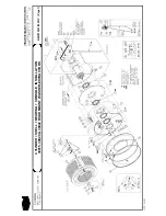
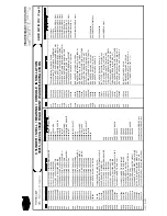
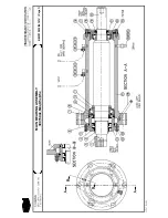
NOTE: See the appropriate bearing assembly drawing.
If no water or metal particles are present in drained oil, replace seals and o-rings as follows. If bearing oil
contains water or metal particles, see “Replacing Bearings with Bearing Housing in Place” below.
1. Remove front shaft seal holder (push-off holes are provided).
2. Inspect the shaft seal sleeve for nicks, gouges, or excessive wear. If a replacement is necessary, heat and tap
the damaged sleeve off of the shaft. Before installing the new sleeve, ensure that the shaft and sleeve are
clean and free from oil. Apply Loctite 271 to the inside of the sleeve, tap sleeve onto the shaft, then remove
excess Loctite.
3. Replace the seals and o-rings. Apply Loctite 271 to the outside of the seals and install in shaft seal holder.
Ensure that the new seals are parallel within the shaft seal holder. Use Loctite 242 when re-installing the
front seal holder bolts.
Ê
Replacing Bearings with Bearing Housing In Place
NOTE: Set bearing clearances only if major components of the original bearing housing (front shaft seal
holder, rear seal/bearing holder, shaft, or shims) are replaced. See “Setting Clearances” in this section after
replacing major components.
Often, the bearing housing does not need to be removed to change the bearings. Remove the shell and bearing
housing only if insufficient space exists for the following procedures, or if the bearing housing (or housing major
components) must be replaced:
1. Remove the front shaft seal holder and rear seal/bearing holder (containing the rear bearing). Note the
position and number of shims under the rear seal/bearing holder. The shims must be installed exactly as
removed.
2. Remove the main shaft, front bearing, and bearing cup through the front of the bearing housing. Remove and
discard used bearings, cups, seals, and o-rings.
3. Install a new seal, bearing, and cup in the rear seal/bearing holder. Install the shims and rear seal/bearing holder.
4. Press a new front bearing on the shaft then guide the shaft into the rear seal/bearing holder. Do not scrape the
new bearings against the inside of the bearing housing.
5. Center the shaft within the housing, then gently tap in the front bearing cup. Install the front shaft seal holder.
The shaft should turn in the housing.
Summary of Contents for 30015
Page 6: ......
Page 8: ......
Page 10: ......
Page 19: ...Section 1 Service and Maintenance ...
Page 51: ...Section 2 Drive Assemblies ...
Page 59: ...BMP950003 95107V Page 1 MOTOR MOUNT 30015 30020 S4A S4G S4J S4T ...
Page 68: ......
Page 69: ...Section 3 Bearing Assemblies ...
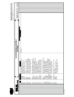
Page 72: ...BMP910032 96141V Page 1 MAIN BEARING ASSEMBLY 30015C4x M4x K5x S5x ...
Page 74: ...BMP910033 96141V Page 1 MAIN BEARING ASSEMBLY ...
Page 76: ...BMP910034 95116V Page 1 MAIN BEARING ASSEMBLY 30015M6x ...
Page 80: ...BMP910035 93251V Page 1 JACKSHAFT ASSEMBLY 30015 30020 30022 RIGID MOUNT WASHER EXTRACTORS ...
Page 82: ......
Page 83: ...Section 4 Shell and Door Assemblies ...
Page 86: ...BMP920009 94491V Page 1 DOOR ASSEMBLY 30015 30020 RIGID MOUNT WASHER EXTRACTORS ...
Page 90: ......
Page 91: ...Section 5 Control and Sensing Devices ...
Page 100: ...BMP920010 97281V Page 1 COIN ASSEMBLY INSTALLATION 240V 30015 30020 30022 COIN MACHINES ...
Page 105: ...Section 6 Chemical Supply Devices ...
Page 113: ...Section 7 Water and Steam Piping and Assemblies ...
Page 114: ...ISOMETRIC SYMBOLS STANDARD SYMBOLS BMP920008 93027V Page 1 SCHEMATIC SYMBOLS KEY ...
Page 132: ...BMP920021 93251V Page 1 STEAM INSTALLATION 30015 30020 30022 RIGID MOUNT WASHER EXTRACTORS ...
Page 138: ...BMP920017 93251V Page 1 ELECTRIC DRAIN VALVE 30015 30020 30022 RIGID MOUNT WASHER EXTRACTORS ...

