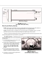
On 30020 and 30022 Machines—Remove the rear
bearing housing and rear reinforcing plate mounting bolts.
1. Remove the rear reinforcing plate very carefully, noting
the position of bearing support tap strips and shims.
Note the position of the shims; they must be replaced
in the same position.
2. Remove the bearing housing from the frame. Remove
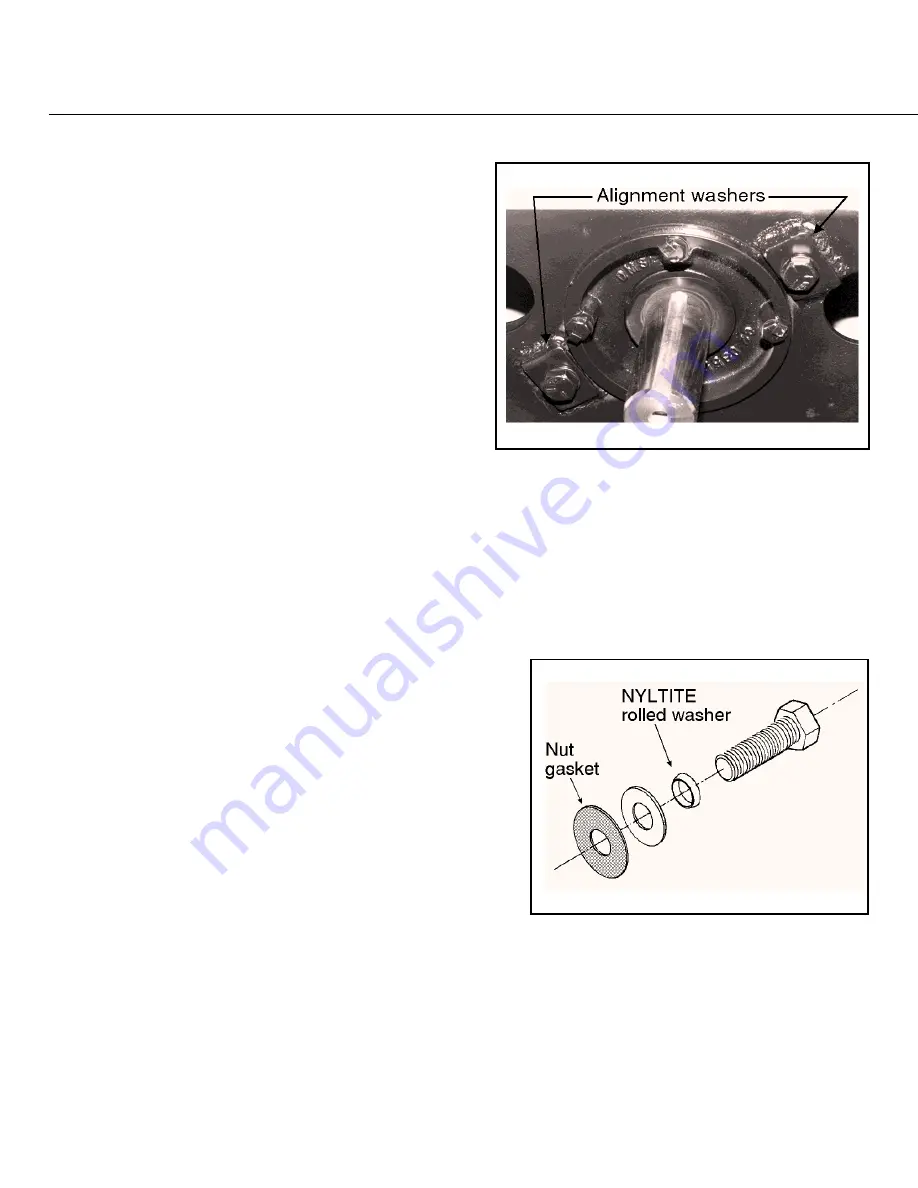
plate and grind off the alignment washers (as shown in
FIGURE 4). and discard old alignment washers.
3. Grind rear reinforcing plate smooth in preparation for
main bearing re-installation.
Ë
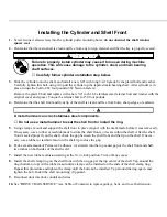
Installing the Bearing Housing and Shell
NOTE 1: Use new bolts when reassembling the machine.
NOTE 2: Apply Permatex 2C adhesive (or equivalent)
to both sides of the new bearing housing gaskets.
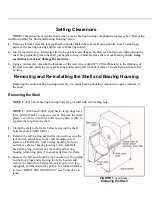
NOTE 3: Install a new NYLTITE washer and nut gasket on each new shell bolt (see FIGURE 5).
On 30015 Machines—Replace the four J-type nuts along the rim of the front console with new clips.
1. Determine that all threaded holes are clean and in good condi-
tion by screwing a new bolt into each hole (if necessary, tap
out any damaged threads).
2. Position the bearing housing in the console.
3. Mount the gasket on the front of the bearing housing.
4. Determine that the shell is clean and free from any old gasket
material, then mount the shell onto the console using new
shell bolts (FIGURE 5).
5. Using drift pins, install the rear shell bolts first (FIGURE 1),
then tighten to draw the shell into place.
6. Install all other shell bolts and tighten evenly. Liberally apply
Dow Corning RTV 732 sealant over the inside shell bolts
and washers.
7. Mount the gasket and the new ring to the inside of the shell.
8. Install the front bearing mounting bolts through the ring and bearing housing, and tighten front bolts. Install
new alignment washers and original shims on rear mounting bolts (FIGURE 2). Replace the shims on rear
mounting bolts exactly as removed.
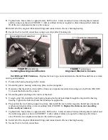
9. Tighten bolts. Insure there is approximately .0625 inch (1.6 mm) clearance between the alignment washers
and the console as shown in FIGURE 7. Add or subtract shims as required to obtain the specified clearance.
Weld the new alignment washers to the console.
10. Install all of the original lubrication fittings and connections to the new bearing housing.
11. Secure the level switch sensor hose using a new clip and self-locking nut.
On 30020 and 30022 Machines—Replace the four J-type nuts and determine that all threaded holes are clean
and in good condition.
1. Position the bearing housing in the console.
2. Mount the gasket, housing reinforcing plate, and second gasket.
3. Determine that the shell is clean and free from any old gasket material, then using new shell bolts (FIGURE
5), mount the shell onto the console.
4. Mount the gasket and ring to the inside of the shell.
5. Using Loctite 504, install the front bearing housing bolts and lockstraps through the ring and the bearing
housing. Tighten the bolts and bend the lockstraps as applicable.
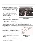
6. Pre-position the two bearing support tap strips, then install the rear reinforcing plate. Install new alignment
washers and original shims on rear mounting bolts (FIGURE 6). Replace the shims on rear mounting
bolts exactly as removed.
7. Tighten bolts. Insure there is approximately .0625 inch (1.6 mm) clearance between the alignment washer and
the reinforcing plate as shown in FIGURE 7. Add or subtract shims as required to obtain specified clear-
ance. Weld the new alignment washers to the reinforcing plate.
8. Install all of the original lubrication fittings and connections to the new bearing housing.
9. Secure the level switch sensor hose.
Î
FIGURE 5
(MSSM0708BE)
Î
Shell Bolt
New alignment washer
Shims
Î
FIGURE 6
(MSSM0708BE)
Î
Installing New Alignment Washers
Î
FIGURE 7
(MSSM0708BE)
Î
Alignment Washer to Console
Î
FIGURE 4
(MSSM0708BE)
Î
Alignment Washers
30020 and 30022 Models
Summary of Contents for 30015
Page 6: ......
Page 8: ......
Page 10: ......
Page 19: ...Section 1 Service and Maintenance ...
Page 51: ...Section 2 Drive Assemblies ...
Page 59: ...BMP950003 95107V Page 1 MOTOR MOUNT 30015 30020 S4A S4G S4J S4T ...
Page 68: ......
Page 69: ...Section 3 Bearing Assemblies ...
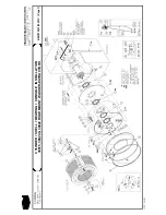
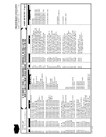
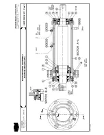
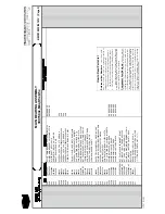
Page 72: ...BMP910032 96141V Page 1 MAIN BEARING ASSEMBLY 30015C4x M4x K5x S5x ...
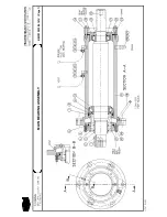
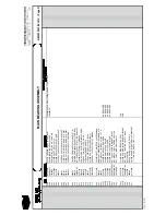
Page 74: ...BMP910033 96141V Page 1 MAIN BEARING ASSEMBLY ...
Page 76: ...BMP910034 95116V Page 1 MAIN BEARING ASSEMBLY 30015M6x ...
Page 80: ...BMP910035 93251V Page 1 JACKSHAFT ASSEMBLY 30015 30020 30022 RIGID MOUNT WASHER EXTRACTORS ...
Page 82: ......
Page 83: ...Section 4 Shell and Door Assemblies ...
Page 86: ...BMP920009 94491V Page 1 DOOR ASSEMBLY 30015 30020 RIGID MOUNT WASHER EXTRACTORS ...
Page 90: ......
Page 91: ...Section 5 Control and Sensing Devices ...
Page 100: ...BMP920010 97281V Page 1 COIN ASSEMBLY INSTALLATION 240V 30015 30020 30022 COIN MACHINES ...
Page 105: ...Section 6 Chemical Supply Devices ...
Page 113: ...Section 7 Water and Steam Piping and Assemblies ...
Page 114: ...ISOMETRIC SYMBOLS STANDARD SYMBOLS BMP920008 93027V Page 1 SCHEMATIC SYMBOLS KEY ...
Page 132: ...BMP920021 93251V Page 1 STEAM INSTALLATION 30015 30020 30022 RIGID MOUNT WASHER EXTRACTORS ...
Page 138: ...BMP920017 93251V Page 1 ELECTRIC DRAIN VALVE 30015 30020 30022 RIGID MOUNT WASHER EXTRACTORS ...

