

Ê
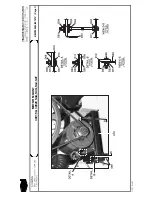
Installing the Cylinder and Shell Front
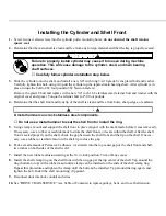
1. Screw two new allen screws into the cylinder puller mounting holes; do not obstruct the shaft retainer
spacer seat.
2. Determine that the main shaft is clean and free from any foreign material and that the key is properly seated.
Failure to properly install cylinder may cause it to loosen during machine
operation. This will cause damage to the cylinder, shell, and main bearing
shaft surfaces.
☞
Carefully follow cylinder installation step below.
3. Slide the cylinder onto the shaft, and install a new 3/4" inch long 3/4-10 grade 8 zinc plated bolt and washer.
Carefully tighten this bolt, using it to pull the cylinder up the tapered main bearing shaft. After cylinder is in
place, torque the bolt to 282 foot pounds (382 Newton meters).
Remove the grade 8 bolt and replace with a new 3/4" inch 18-8 stainless steel retainer bolt and washer with the
original cover and spacer. Torque the retainer bolt to 150 foot pounds.
4. Determine that the shell front and front lip of the shell is clean and free from burrs, sharp edges, or sealants.
A metal hammer can crack stainless steel components.
☞
Do not use a metal hammer to seat the shell front or install the ring.
5. Using clamps, mount and support the shell front in place (align it with the mark made before it was removed).
If necessary, use a rubber or rawhide maul to strike the shell front so it seats within the shell. After the shell
front is seated properly on the shell, check the gap between the shell front and the lip on the shell. If neces-
sary, use a rubber or rawhide maul on the shell lip to close the gap.
6. Pack a small amount of Permatex 2 adhesive (or similar) into the top center gap of the shell front and shell,
two inches on both sides of the shell weld.
7. Install the new rubber extrusion starting at the 10 o’clock position. Trim off any excess.
8. Install the shell clamp ring on the shell front with the ring gap at the top center of the shell. Tap around the
ring (bottom to top) with a rubber maul until a clamp can be installed on the ends of the shell clamp ring.
Repeat this procedure and tighten the clamp until the bolt can be installed. Tap around the ring again, and
tighten the bolt. Install the shell mount ring clip guard.
9. Reconnect door interlock conduit and wires.
10. See “DRIVE TRAIN SERVICE” (see Table of Contents) to replace pulleys, belts, and to set belt tension.
Summary of Contents for 30015
Page 6: ......
Page 8: ......
Page 10: ......
Page 19: ...Section 1 Service and Maintenance ...
Page 51: ...Section 2 Drive Assemblies ...
Page 59: ...BMP950003 95107V Page 1 MOTOR MOUNT 30015 30020 S4A S4G S4J S4T ...
Page 68: ......
Page 69: ...Section 3 Bearing Assemblies ...
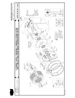
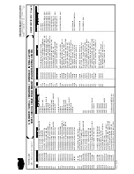
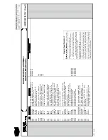
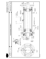
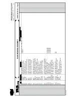
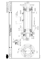
Page 72: ...BMP910032 96141V Page 1 MAIN BEARING ASSEMBLY 30015C4x M4x K5x S5x ...
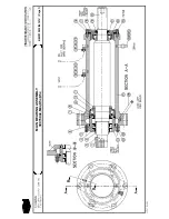
Page 74: ...BMP910033 96141V Page 1 MAIN BEARING ASSEMBLY ...
Page 76: ...BMP910034 95116V Page 1 MAIN BEARING ASSEMBLY 30015M6x ...
Page 80: ...BMP910035 93251V Page 1 JACKSHAFT ASSEMBLY 30015 30020 30022 RIGID MOUNT WASHER EXTRACTORS ...
Page 82: ......
Page 83: ...Section 4 Shell and Door Assemblies ...
Page 86: ...BMP920009 94491V Page 1 DOOR ASSEMBLY 30015 30020 RIGID MOUNT WASHER EXTRACTORS ...
Page 90: ......
Page 91: ...Section 5 Control and Sensing Devices ...
Page 100: ...BMP920010 97281V Page 1 COIN ASSEMBLY INSTALLATION 240V 30015 30020 30022 COIN MACHINES ...
Page 105: ...Section 6 Chemical Supply Devices ...
Page 113: ...Section 7 Water and Steam Piping and Assemblies ...
Page 114: ...ISOMETRIC SYMBOLS STANDARD SYMBOLS BMP920008 93027V Page 1 SCHEMATIC SYMBOLS KEY ...
Page 132: ...BMP920021 93251V Page 1 STEAM INSTALLATION 30015 30020 30022 RIGID MOUNT WASHER EXTRACTORS ...
Page 138: ...BMP920017 93251V Page 1 ELECTRIC DRAIN VALVE 30015 30020 30022 RIGID MOUNT WASHER EXTRACTORS ...