


Summary of Contents for 30015
Page 4: ......
Page 6: ...2 ...
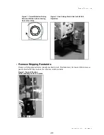
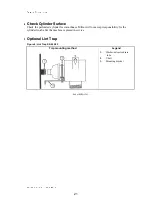
Page 17: ...Section 1 Installation 13 ...
Page 26: ...22 ...
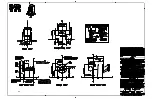
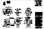
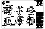
Page 27: ...Section 2 Dimensional Drawings 23 ...
Page 28: ...24 ...
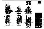
Page 29: ...25 ...
Page 30: ...26 ...
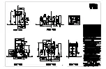
Page 31: ...27 ...
Page 32: ...28 ...
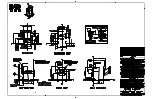
Page 33: ...29 ...
Page 34: ...30 ...
Page 35: ...31 ...
Page 36: ...32 ...
Page 37: ...33 ...
Page 38: ...34 ...
Page 39: ...35 ...


