


MSIN0704AE/9271BV (1 of 2)
È
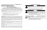
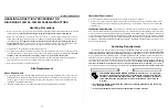
RIGID MOUNT WASHER-EXTRACTOR
INSTALLATION AND SERVICE SAFETY
Ê
Hazards During Assembly
ELECTROCUTION HAZARD—Contact with high voltage can kill or seriously in-
jure you.
☞
All electrical connections must be made by a competent electrician.
Ê
Hazards During Servicing and Maintenance
ELECTROCUTION HAZARD—High voltage is present inside electric boxes, mo-
tors and many other components. Power switches on machine control panels
disable only control circuit power in certain boxes. You can be killed or seri-
ously injured on contact with high voltage.
☞
Lock OFF and tag out power at the wall disconnect before servicing, except
where specifically instructed otherwise in this manual.
ENTANGLE AND CRUSH HAZARD—Belts and pulleys can entangle and crush
body parts.
☞
Lock OFF and tag out power at the wall disconnect before servicing, except
where specifically instructed otherwise in this manual.
☞
Insure belt guards are in place during service procedures.
B
Ê
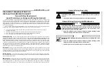
General Safety Requirements
(specific warnings, next page and throughout manual)
Incorrect installation, neglected preventive maintenance, abuse, and/or improper repairs or changes to the
machine can cause unsafe operation and personal injuries, such as multiple fractures, amputations, or death. The
owner or his selected representative (owner/user) is responsible for understanding and ensuring the proper operation
and maintenance of the machine. The owner/user must familiarize himself with the contents of all machine instruc-
tion manuals. The owner/user should direct any questions about these instructions to a Milnor
®
dealer or the Mil-
nor
®
Service department.
Most regulatory authorities (including OSHA in the USA) hold the owner/user ultimately responsible for
maintaining a safe working environment. Therefore, the owner/user must do the following:
•
recognize all foreseeable safety hazards within his facility and take actions to protect his personnel,
equipment, and facility
•
require that personnel are familiar with all functional and safety aspects of the machine
•
ensure safety devices installed on the machine are in place and properly maintained
•
ensure all machine parts and assemblies are properly maintained.
Ë
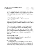
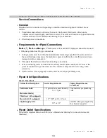
Laundry Facility
—Provide a supporting floor that is strong and rigid enough to support--with a reasonable
safety factor and without undue or objectionable deflection--the weight of the fully loaded machine and the forces
transmitted by it during operation. (For washer-extractors, see “ABOUT THE FORCES TRANSMITTED BY MIL-
NOR
®
WASHER-EXTRACTORS.”) Provide sufficient clearance for machine movement. Provide any safety
guards, fences, restraints, devices, and verbal and/or posted restrictions necessary to prevent personnel, machines,
or other moving machinery from accessing the machine or its path. Provide adequate ventilation to carry away heat
and vapors. Ensure service connections to installed machines meet local and national safety standards, especially
regarding the electrical disconnect (see the National Electric Code). Prominently post safety information, including
signs showing the source of electrical disconnect.
Ë
Personnel
—Inform personnel about hazard avoidance and the importance of care and common sense. Provide
personnel with the safety and operating instructions that apply to them. Verify that personnel use proper safety and
operating procedures. Verify that that personnel understand and abide by point-of-hazard tags on the machine and
procedure-specific precautions in the instruction manuals.
Ë
Safety Devices
—Ensure that no one eliminates or disables any safety device on the machine or in ths facility.
Do not allow machine to be used with any missing guard or cover. Service any failing or malfunctioning device
before operating the machine.
Ë
Maintenance
—Ensure the machine is inspected and serviced in accordance with the norms of good practice and
with the preventive maintenance schedule. Replace belts, pulleys, brake shoes/disks, clutch plates/tires, rollers,
seals, alignment guides, etc. before they are severely worn. Immediately investigate any evidence of impending
failure and make needed repairs (e.g., cylinder, shell, or frame cracks; drive components such as motors, gear boxes,
5
Summary of Contents for 30015
Page 4: ......
Page 6: ...2 ...
Page 17: ...Section 1 Installation 13 ...
Page 26: ...22 ...
Page 27: ...Section 2 Dimensional Drawings 23 ...
Page 28: ...24 ...
Page 29: ...25 ...
Page 30: ...26 ...
Page 31: ...27 ...
Page 32: ...28 ...
Page 33: ...29 ...
Page 34: ...30 ...
Page 35: ...31 ...
Page 36: ...32 ...
Page 37: ...33 ...
Page 38: ...34 ...
Page 39: ...35 ...


