Ë
Foundation Requirements
—The floor and/or all other support components must have sufficient strength
(and rigidity with due consideration for the natural or resonant frequency thereof) to withstand the fully loaded
weight of the machine, including the wet goods and any repeated sinusoidal (rotating) forces generated during its
operation. Determining the suitability of floors, foundations, and other supporting structures normally requires
analysis by a qualified structural engineer.
Ë
Drain Requirements
—An open trench must be provided
in the floor for draining. Its size (as a minimum) and location
(centered under the drain valve) should be as shown on the
dimensional drawing and with a minimum slope of 1/8" per foot
to the sewer. Even where one trench serves several machines,
the cross section area of the trench shown on the dimensional
drawing is normally acceptable since draining is intermittant
and the portion of the trench located under each machine is suf-
ficient to contain most, if not all, of the outfall from one machine.
Refer to local codes for sanitary requirements such as traps, etc.
Ê
Setting Procedures
To protect against lateral “creeping” of the machine during operation, due to vibration, roughen the area of the
floor where grout will be applied. Anchor bolts are
required for most of the models covered by this document
(refer to the machine dimensional drawing). Once
the foundation is prepared, the shipping skids are removed
and the machine is ready to be set in its desired position.
See FIGURES 3 and 7, then proceed as follows:
1. Lower the machine onto three short lengths of 2 x 4’s such that the shell front is resting on two of them and
the third is centered under the shell back.
2. Put shims on top of the 2 x 4’s until
the machine has approximately 1"
clearance under each base pad and
is level. Check level as shown in
FIGURE 3.
3. When the machine is level and has
room for 1" of grout under each
base pad, apply the grout. Fill all
holes under the base pads so that
each pad is resting upon a solid
base of grout.
4. When the grout has hardened, tighten
down the anchor bolts and
remove the four hold down bolts.
The shell will be lifted by the
Hydro-cushion
®
cylinders so that
the 2 x 4 blocking may be removed.
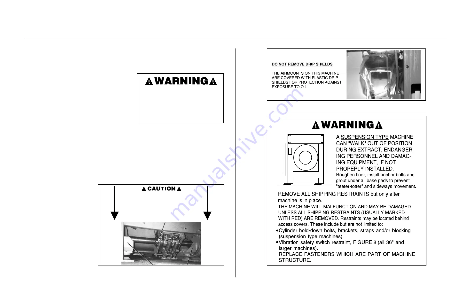
REMOVE SHIPPING RESTRAINTS BEFORE
ATTEMPTING TO RUN MACHINE but only
after machine is in place. Restraints are usually
marked with red, and may be concealed behind
access panels.
REPLACE THOSE FEATURES WHICH ARE
PART OF MACHINE STRUCTURE.
Î
FIGURE 4
(MSIN0301AE)
Î
Shipping Restraints
WITH SKIDS REMOVED THERE IS MINIMAL
CLEARANCE BETWEEN BRAKE SHOE ARMS
AND GROUND.
BE CAREFUL NOT TO DAMAGE THESE PARTS WHEN
MOVING THIS EQUIPMENT. MANUFACTURER NOT
RESPONSIBLE FOR CONCEALED DAMAGE. INSPECT
BRAKE ARMS TO PROTECT YOUR INTEREST.
Î
FIGURE 5
(MSIN0301AE)
Î
60" and 72" Staph-Guard
®
Î
FIGURE 6
(MSIN0301AE)
Î
Drip Shields
Î
FIGURE 7
(MSIN0301AE)
Î
Anchor and Grout Warning
31
Summary of Contents for 42044SR2
Page 2: ......
Page 4: ......
Page 8: ......
Page 9: ...Installation 1 5 ...
Page 37: ...Î FIGURE 8 MSIN0301AE Î Vibration Switch Î FIGURE 9 MSIN0301AE Î 60 Staph Guard 33 ...
Page 51: ...586DA4 BUecU CicdU CSXU QdYS B5EC5 D1 9 CD1 1D9 1 4 5B1D9 C9 1 15 1F _V 47 ...
Page 53: ...Dimensional Drawings 2 49 ...
Page 54: ......
Page 55: ...51 ...
Page 56: ...52 ...
Page 57: ...53 ...
Page 58: ...54 ...
Page 59: ...55 ...
Page 60: ...56 ...
Page 61: ...57 ...
Page 62: ...58 ...
Page 63: ...59 ...
Page 64: ......
Page 65: ...61 ...
Page 66: ...62 ...
Page 67: ...63 ...
Page 68: ...64 ...

