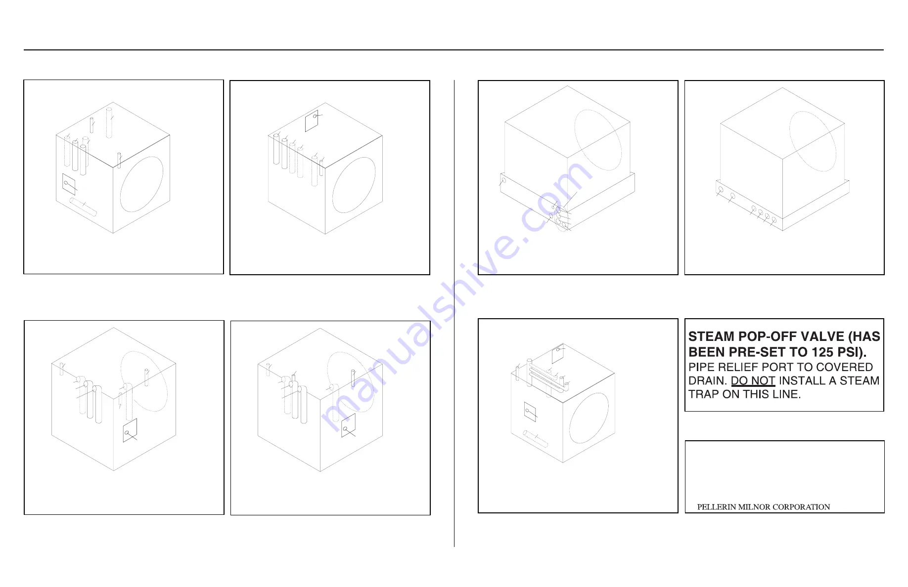
Valves
on left side
42031WPx
42031SPx
42044WPx
42044SPx
1. Hot
2. Cold
3a. "Third" water
3b. "Reuse" water
4a. Steam (WPx)
4b. Steam (SPx)
5. Compressed air (WPx)
6. Compressed air (SPx)
E. Electric connection
4b
E
4a
3b
5b
5a
3a
2
1
Î
FIGURE 2
(MSIN0201BE)
Î
42031, 42044 Non-Tilting, Open Pocket and
Staph-Guard
®
Service Connections
Valves
on left side
42026QHP
48032BHP
48036QHP
1. Cold
2. Hot
3. "Third" water
4. Steam
5. "Reuse" water
6. Compressed air
E. Electric connection
1
2
3
4
5
6
E
Î
FIGURE 3
(MSIN0201BE)
Î
42026, and 42032 Non-Tilting,
Open Pocket Service Connections
Valves
on rear
60044WPx
1. Hot
2. Cold
3a. "Third" water
3b. "Reuse" water
4. Steam
5. Compressed air
6. Spraydown/Cooldown
E. Electric connection
6
5
3b
4
3a
2
1
E
Î
FIGURE 4
(MSIN0201BE)
Î
60044 Non-Tilting, Open Pocket
Service Connections
Valves
on rear
72044WPx
1. Hot
2. Cold
3a. "Third" water
3b. "Reuse" water
4. Steam
5. Compressed air
6. Spraydown/Cooldown
E. Electric connection
6
4
5
3b
3a
2
1
E
Î
FIGURE 5
(MSIN0210BE)
Î
72044 Non-Tilting, Open Pocket
Service Connections
72044WTx
52038WTx
1. Hot
2. Cold
3. "Third" or "Reuse" water
4a. Steam (72044WTx)
4b. Steam
(52038WTx)
5. Compressed air
E. Electric connection
4b
E
4a
3
2
1
5
Î
FIGURE 6
(MSIN0201BE)
Î
72044 and 52038 Tilting,
Open Pocket Service Connections
Valves
on rear
48032BTx
48036QTx
1. Hot
2. Cold
3. "Third" or
"Reuse"water
4. Steam
5. Compressed air
E. Electric connection
E
4
3
2
1
5
Î
FIGURE 7
(MSIN0201BE)
Î
48032, 48036 Tilting, Open Pocket
Service Connections
Valves
on left side
52038WP1
60044SPx
72044WP1
72044SPx
1. Hot
2. Cold
3a. "Third" water
3b. "Reuse" water
4. Steam
5. Compressed air
Ea. Electric connection
(52038WP1, 72044WP1)
Eb. Electric connection
(60044SPx, 72044SPx)
4
5
3b
3a
1
2
Eb
Ea
Î
FIGURE 8
(MSIN0201BE)
Î
52038 and 60044 Non-Tilting Open Pocket
and Staph-Guard
®
Service Connections
Î
FIGURE 9
(MSIN0201BE)
Î
Indirect Steam Machines Only
Please check perforated cylinder for smoothness
before placing machine in service.
We cannot accept claims for damage to cylinder’s
smooth finish after machine has been placed in
service.
Î
FIGURE 10
(MSIN0201BE)
Î
All Machines
37
Summary of Contents for 42044SR2
Page 2: ......
Page 4: ......
Page 8: ......
Page 9: ...Installation 1 5 ...
Page 37: ...Î FIGURE 8 MSIN0301AE Î Vibration Switch Î FIGURE 9 MSIN0301AE Î 60 Staph Guard 33 ...
Page 51: ...586DA4 BUecU CicdU CSXU QdYS B5EC5 D1 9 CD1 1D9 1 4 5B1D9 C9 1 15 1F _V 47 ...
Page 53: ...Dimensional Drawings 2 49 ...
Page 54: ......
Page 55: ...51 ...
Page 56: ...52 ...
Page 57: ...53 ...
Page 58: ...54 ...
Page 59: ...55 ...
Page 60: ...56 ...
Page 61: ...57 ...
Page 62: ...58 ...
Page 63: ...59 ...
Page 64: ......
Page 65: ...61 ...
Page 66: ...62 ...
Page 67: ...63 ...
Page 68: ...64 ...


