background image

Page (1 / 3)

PELLERIN MILNOR CORPORATION

PELLERIN MILNOR CORPORATION

6

1

1

1

1

5

2

2

3

3

4

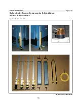
Figure 1: Replacement parts

BMP150061/2016046A

Safety Light Screen Components & Installation

48040M7K, 68036M5K, 72046M5K

2

2

16

Summary of Contents for 48040M7K

Page 1: ...l Number ECN MPI4840MAE 2016175A Publishing System TPAS2 Access date 04 21 2016 Document ECNs Latest Installation and Service 48040M7K PELLERIN MILNOR CORPORATION POST OFFICE BOX 400 KENNER LOUISIANA 70063 0400 U S A ...

Page 2: ......

Page 3: ...2015443A 39 2 Installation 40 48040F_ 48040H_ 68036H_ Washer Extractor Installation BIIFLI01AC 20140321 45 About the Forces Transmitted by Milnor Washer extractors BIWUUI02 20001108 47 Shipping Brackets BMP150056 2016046A 49 Service Connections BIIFUI01FG 20130129 53 3 Drive 54 Drive Components and Belt Installation BIIFLM05 20151104 57 Motor Mount 48040M7M BMP150036 2015386A 60 Disc Brake Mainten...

Page 4: ... 122 Water 48040M7K BMP150062 2016046A 127 Steam BMP150063 2016046A 129 Installation Drain Valve Body With One Valve BIIFLM21 20120503 131 Drain Valve Body with Two Valves BIIH4M03 20120502 133 8 Chemical 134 Soap Chute BMP150052 2016064A 136 Eight Port Peristaltic Supply Manifold BMP150053 2015292A 139 9 Control and Sensing Assemblies 140 Switch Panel Pivot Arm BMP150050 2015435A 142 Tilt Limit S...

Page 5: ...is warranty For parts which require routine replacement due to normal wear such as gaskets contact points brake and clutch linings belts hoses and similar parts the warranty time period is 90 days We reserve the right to make changes in the design and or construction of our equipment including purchasedcomponents withoutobligationtochangeanyequipmentpreviouslysupplied ANY SALE OR FURNISHING OF ANY...

Page 6: ...ou can also get components from the Milnor factory Tell the supplier the machine model and serial number and this data for each necessary component The component number from this manual The component name if known The necessary quantity The necessary transportation requirements If the component is an electrical component give the schematic number if known If the component is a motor or an electric...

Page 7: ...rporation These words are trademarks of Pellerin Milnor Corporation Table 1 Trademarks AutoSpot E P Plus Linear Costa Master MilTouch Ram Command CBW ExactXtract Linear Costo MilTouch EX RecircONE Drynet Gear Guardian Mentor Miltrac RinSave E P Express GreenTurn Mildata MultiTrac SmoothCoil E P OneTouch GreenFlex Milnor PBW Staph Guard Hydro cushion MilMetrix PulseFlow End of BIUUUD14 3 ...

Page 8: ......

Page 9: ...Safety 1 5 ...

Page 10: ...cted to those employees given the task of using it only specifically designated workers carry out repairs modifications maintenance or servicing information instruction and training is provided workers and or their representatives are consulted Work equipment must comply with the requirements listed below The owner user must verify that installation and maintenance of equipment is performed in suc...

Page 11: ...ided on the machine safety placards in the Safety Guide and throughout the other machine manuals Placards must be kept clean so that the information is not obscured They must be replaced immediately if lost or damaged The Safety Guide and other machine manuals must be available at all times to the appropriate personnel See the machine service manual for safety placard part numbers Contact the Miln...

Page 12: ...ed door The moving door can strike you or crush or pinch your limbs if caught between the door and machine Some doors move automatically Keep yourself and others clear of movement areas and paths Keep both hands on the controls while operating Do not operate the machine with malfunctioning two hand manual controls WARNING 5 Crush Hazards Tilting machines only The machine can crush your body or lim...

Page 13: ...e with a malfunctioning door interlock Open pocket machines only Keep yourself and others clear of cylinder and goods during jogging operation Do not operate the machine with malfunctioning two hand manual controls WARNING 9 Confined Space Hazards Confinement in the cylinder can kill or injure you Hazards include but are not limited to panic burns poisoning suffocation heat prostration biological ...

Page 14: ...ll or injure personnel further damage or destroy the machine damage property and or void the warranty Do not operate a damaged or malfunctioning machine Request authorized service WARNING 17 Explosion Hazards Cylinder A damaged cylinder can rip apart during extraction puncturing the shell and discharging metal fragments at high speed Do not operate the machine with any evidence of damage or malfun...

Page 15: ...t tagout standard when lockout tagout is called for in the service instructions Outside the USA abide by the OSHA standard in the absence of any other overriding standard WARNING 22 Crush Hazards Tilting machines only The machine housing will crush your body or limbs if it descends or falls while you are under it Housing can descend with power off or on Manual operation of tilting valves overrides...

Page 16: ...ng unless both safety stands are installed and power is locked out tagged out Do not work near the raised shell or housing with power on unless both safety stands are installed Install these safety components using the procedure prescribed in this document Maintain these safety components in good condition Designate a convenient secure area to stow these safety components when not in use Figure 1 ...

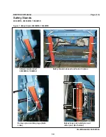
Page 17: ...036M5K 7246M5K Safety stands released and locked in place Extend legs and install pins and cotter pins Both sides Remove pins and drop legs Both sides 1 1 2 2 3 4 3 4 3 4 3 4 Figure 1 Safety Stands 68036M5K 72046M5K BMP150055 2016046A Safety Stands 48040M7K 68036M5K 72044M5K 5 6 7 5 6 7 13 ...

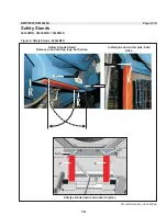
Page 18: ... Safety Stands 48040M7K Safety Stands Safety Stands Stored Remove pins and drop legs both sides Install pins and cotter pins both sides BMP150055 2016046A 48040M7K 68036M5K 72044M5K 8 9 5 6 7 3 4 3 4 5 6 7 Safety stands down and locked in place 14 ...

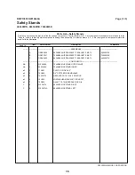
Page 19: ...5 2016046A Safety Stands 48040M7K 68036M5K 72044M5K ASSEMBLIES A GSB68002 6836M5K SHIPPING SAFETY BRACKETS INSTL 68036M5K B GSB72001 7246M5K SHIPPING SAFETY BRACKETS INSTL 72046M5K C GSB68002 6836M5K SHIPPING SAFETY BRACKETS INSTL 48040M7K COMPONENTS AB 1 W2 25098 7246M5K KICKSTAND OUTER WLMT AB 2 02 25098A 7246M5K KICKSTAND INNER all 3 17A057 CLEVIS PIN 3 4 X6 5 all 4 15H062 3 4 COTTERPIN REMOVAB...

Page 20: ... 1 3 PELLERIN MILNOR CORPORATION PELLERIN MILNOR CORPORATION 6 1 1 1 1 5 2 2 3 3 4 Figure 1 Replacement parts BMP150061 2016046A Safety Light Screen Components Installation 48040M7K 68036M5K 72046M5K 2 2 16 ...

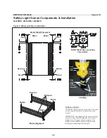
Page 21: ...within the midpoint of the sensor s defined area The upper and lower limits of the defined area are dimensioned in the light screen instruction manual supplied with parts Midpoint Receiver Emitter Mirror Mirror Mirror Alignment Mounting hardware not supplied Pole leveling bolts 4 places supplied Base leveling bolts 4 places supplied Post level supplied Leveling 1 Figure 2 Safety Light Screen Insta...

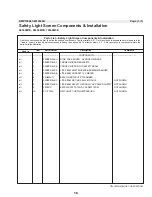
Page 22: ...TS all 1 09RPE018LBG STND FOR SENDER RECEIVER MIRROR all 2 09RPE018LBF CORNER MIRROR BRACKETS all 3 09RPE018LBE CORNER MIRROR FOR SAFETY BEAM all 4 09RPE018LBA LITE BEAM EMITTER RECEIVER 600MM BANNER all 5 09RPE018LBB LITE BEAM CORDSET 15 3 METER all 6 09H025V71 BEACON ROTARY 8 5 DIA AMBER all 7 09RPE018LBC LITE BEAM MUTING RELAY MODULE NOT SHOWN all 8 09RPE018LBD LITE BEAM SAFETY RATING 24VDC POW...

Page 23: ... information may apply to models in addition to those listed above It applies to paper tags It does not apply to the vinyl or metal safety placards which must remain permanently affixed to the machine and replaced if no longer readable Paper tags on the machine provide installation guidelines and precautions The tags can be tie on or adhesive You can remove tie on tags and white adhesive tags afte...

Page 24: ...able from the Milnor Parts department B2TAG88005 This carefully built product was tested and inspected to meet Milnor performance and quality standards by identification mark of tester B2TAG94078 Do not forklift here do not jack here do not step here whichever applies B2TAG94079 Rig for crane lifting either 3 point or 4 point depending on the number of lifting eyes provided using a steep angle on ...

Page 25: ...straints to be removed or components to be installed Do not start the machine until these actions are completed B2T2002013 Do not start the machine until shipping restraints are removed This tag will appear on the outside of the machine to alert you to the presence of internal shipping restraints A tag will also appear on the restraint to help identify it Most but not all shipping restraints displ...

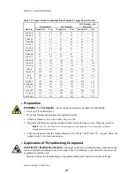
Page 26: ...STM A307 and stainless steel B ASTM A354 Grade BC C SAE Grade 5 ASTM A449 D SAE Grade 8 and ASTM A354 BD 1 Torque Values The tables below list the standard size grade threadlocking compound and torque requirements for fasteners commonly used on Milnor equipment Note 1 Data derived from Pellerin Milnor Corporation Bolt Torque Specification bolt_torque_milnor xls 2002096 1 1 Carbon Steel Fasteners 1...

Page 27: ... 7 8 x 9 167 226 429 582 606 821 531 719 7 8 x 14 184 249 473 641 668 906 1 x 8 250 339 644 873 909 1232 796 1079 1 x 12 274 371 704 954 994 1348 1 x 14 281 381 723 980 1020 1383 1 1 8 x 7 354 480 794 1077 1287 1745 1126 1527 1 1 8 x 12 397 538 891 1208 1444 1958 1 1 4 x 7 500 678 1120 1519 1817 2464 1590 2155 1 1 4 x 12 553 750 1241 1682 2012 2728 1 3 8 x 6 655 888 1469 1992 2382 3230 2085 2827 1...

Page 28: ...2 376 246 329 3 14 x 16 144 192 223 297 315 420 7 8 x 9 125 166 322 430 455 606 398 531 7 8 x 14 138 184 355 474 501 668 1 x 8 188 250 483 644 682 909 597 796 1 x 12 205 274 528 716 746 995 1 x 14 210 280 542 735 765 1037 1 1 8 x 7 266 354 595 807 966 1288 845 1126 1 1 8 x 12 298 404 668 890 1083 1444 1 1 4 x 7 375 500 840 1120 1363 1817 1192 1590 1 1 4 x 12 415 553 930 1261 1509 2013 1 3 8 x 6 49...

Page 29: ...22 30 5 16 x 24 13 18 19 26 27 37 27 37 3 8 x 16 20 27 31 42 44 60 38 52 3 8 x 24 23 31 35 47 50 68 7 16 x 14 32 43 49 66 70 95 61 83 7 16 x 20 36 49 55 75 78 106 1 2 x 13 49 66 75 102 107 145 93 126 1 2 x 20 55 75 85 115 120 163 9 16 x 12 70 95 109 148 154 209 134 182 9 16 x 18 78 106 121 164 171 232 5 8 x 11 97 132 150 203 212 287 186 252 5 8 x 18 110 149 170 230 240 325 Table 8 Torque Values fo...

Page 30: ...ions of LocTite 277 Bolt Grade Grade 2 Grade 5 Grade 8 Grade BC Bolt Size Pound feet N m Pound feet N m Pound feet N m Pound feet N m 1 x 8 325 441 837 1135 1181 1601 1034 1402 1 x 12 356 483 916 1242 1293 1753 1 x 14 365 495 939 1273 1326 1798 1 1 8 x 7 461 625 1032 1399 1674 2270 1464 1985 1 1 8 x 12 516 700 1158 1570 1877 2545 1 1 4 x 7 650 881 1456 1974 2362 3202 2067 2802 1 1 4 x 12 719 975 1...

Page 31: ...3 709 314 425 1 1 4 x 12 504 683 480 651 288 390 1 1 2 x 6 930 1261 888 1204 533 722 1 1 2 x 12 732 992 703 953 422 572 2 Preparation WARNING 1 Fire Hazard Some solvents and primer products are flammable Use in a well ventilated area Do not use flammable products near ignition sources 1 Clean all threads with a wire brush a tap or a die 2 Degrease the fasteners and the mating threads with a cleani...

Page 32: ...compound to the bolt 3 Tighten bolt to value shown in the appropriate table Table 5 through Table 11 3 2 Through Holes 1 Insert bolt through assembly 2 Apply several drops of threadlocking compound to the bolt thread area that will engage the nut 3 Tighten bolt to value shown in the appropriate table Table 5 through Table 11 Figure 3 Through Hole Application Legend A No threadlocking compound here...

Page 33: ...Fastener Torque Requirements PELLERIN MILNOR CORPORATION Figure 4 Disassembly Use Localized Heat Legend A Soldering gun heating small fastener B Torch heating large fastener End of BIUUUM04 29 ...

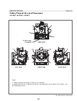
Page 34: ... 68036M5K 72046M5K 20 90 50 Notes 1 Replace placard immediately if removed or unreadable 2 Approximate locations of placards are shown Mounting holes are provided on the machine Use 8 self tapping screws 30 30 REAR VIEW FRONT VIEW RIGHT VIEW LEFT VIEW 40 On steam pipe if equipped 20 20 60 10 10 30 ...

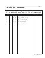
Page 35: ... parts list to the illustration Parts List Safety Placard Use and Placement COMPONENTS all 10 01 10583A NPLT 64 72 W E WARN FRT TCATA all 20 01 10630A NPLT TILT CRUSH HAZARD TCATA all 30 01 10377A NPLT ELEC HAZARD LG TCATA all 40 01 10685A NPLT BURN HAZARD WARN TCATA all 50 01 10648A NPLT GEAR HAZARD TCATA all 60 01 10699A NPLT SERV HZRD PLYEST TCATA all 90 01 10761X NPLT M K SAFETY STANDS PELLERI...

Page 36: ...acement ISO 48040M7K 68036M5K 72046M5K 20 40 Notes 1 Replace placard immediately if removed or unreadable 2 Approximate locations of placards are shown Mounting holes are provided on the machine Use 8 self tapping screws 30 30 REAR VIEW FRONT VIEW RIGHT VIEW LEFT VIEW 20 20 10 10 32 ...

Page 37: ... assembly The item numbers 1 2 3 etc assigned to components relate the parts list to the illustration Parts List Safety Placard Use and Placement COMPONENTS All 10 01 10629Z NPLT TILT M K WARN FRT ISO all 20 01 10630Y NPLT TILT CRUSH HAZARD ISO all 30 01 10377 NPLTE WARNING 4X4 all 40 01 10761X NPLT M K SAFETY STANDS PELLERIN MILNOR CORPORATION Page 2 2 BMP150028 2016075A Safety Placard Use and Pl...

Page 38: ...PELLERIN MILNOR CORPORATION Page 1 5 PELLERIN MILNOR CORPORATION Figure 1 Installed view 1 2 3 6836M5K shown BMP150029 2015443A Guards and Covers 48040M7K 68036M5K 72046M5K 34 ...

Page 39: ...RIN MILNOR CORPORATION Figure 2 Drive covers 7246M5K Drive Covers 6836M5K Drive Covers Brake cover not shown 4 4 5 Jackshaft motor cover Brake cover 6 26 27 28 26 27 28 26 27 28 BMP150029 2015443A Guards and Covers 48040M7K 68036M5K 72046M5K 35 ...

Page 40: ...d See Detail A 7246M5K shown 7 8 See Detail B Detail A Pivot shaft Detail B Pivot shaft Detail C Belt Guard Bolts 4 places Locking 9 10 10 9 12 11 16 17 18 13 23 24 25 Locking Bolts 27 28 29 Typical 19 20 21 22 See Detail C BMP150029 2015443A Guards and Covers 48040M7K 68036M5K 72046M5K 36 ...

Page 41: ...D CYLINDER GUARDS 68036M5K B GGS72003 7246M5K HYD CYINLDER GUARDS 72046M5K C GGS48012 4840M7K HYD CYLINDER GUARDS 48040M7K COMPONENTS A 1 W2 22693 6836M5K SIDEPANEL WLMT RT B 1 W2 25014 7246M5K SIDEPANEL WLMT RT C 1 W2 24044 4840M7K SIDEPANEL WLMT RT A 2 W2 22693A 6836M5K SIDEPANEL WLMT LT B 2 W2 25014A 7246M5K SIDEPANEL WLMT LT C 2 W2 24044A 4840M7K SIDEPANEL WLMT LT all 3 02 22692 6836M5K TILT F...

Page 42: ...BRACKET all 9 X2 22700 6836M5K BELT COVER PIVOT SHAFT all 10 17B012 EXTRETRING IND 1000 50 ST ZD Z A 11 02 22775 6836M5K TRUCK BUMPER BRKT B 11 02 25107 7246M5K TRUCK BUMPER BRKT all 12 60B075 DFW56 33PMSP RUBB CONN all 13 02 22676 6836M5K BELT COVER LOCK BRKT all 14 02 25121A 7246M5K BELTGUARD UPPER FILLER AB 15 AGS75001L COVER GEARTRAIN LH C 15 02 21968A EXTENDED COVER CHAIN COUPLING 4840F TORQU...

Page 43: ...Installation 2 39 ...

Page 44: ... 2 Locate the lift points as shown in Figure 1 3 Attach chains as shown in Figure 2 Figure 1 Where To Lift Figure 2 Rigger liable for damages CAUTION 1 Machine damage hazard Improper placement of pickup chains can cause direct or indirect damage to machine Use a 4 point pickup as shown in Figure 2 Use long pickup chains to prevent racking and or twisting machine frame 2 Moving the Machine into Pla...

Page 45: ...other support components must have sufficient strength and rigidity with due consideration for the natural or resonant frequency thereof to withstand the fully loaded weight of the machine including the wet goods and any repeated sinusoidal rotating forces generated during its operation Determining the suitability of floors foundations and other supporting structures normally requires analysis by ...

Page 46: ...clearance between base pads and existing foundation floor Voids must not exist 3 Tighten anchor bolts evenly using only one quarter turn on each bolt before moving to the next one While tightening frequently skip from front to back and right to left to insure uniform tension After tightening all bolts check each bolt at least twice during the first week of operation 5 Before Running Machine CAUTIO...

Page 47: ...hold down weldment Cone can weldment as shipped locking the shell and mid frame together Cup weldment when setup for operation Figure 5 Shims stored under the mid frame 6 Before Tilting Machine WARNING 5 Crush Sever hazard Tilting mechanisms can crush or sever parts of your body caught in them 43 ...

Page 48: ...ALWAYS visually inspect the tilt wheels to be sure they are all fully seated in their cradles before each manual tilt up Pneumatic valve manual operation must be done by trained competent maintenance personnel who thoroughly understand the system and all the consequences of manual operations ALWAYS understand beforehand all the consequences of manually operating pneumatic valves NEVER permit opera...

Page 49: ...ty to safely withstand our published forces without transmitting undue vibration If the subsoil has subsided or if the floor slab itself has insufficient strength and rigidity a deeper foundation poured as to become monolithic with the floor slab may be required Support pilings may even be required if the subsoil itself is springy i e if its resonant frequency is near the operating speed of the ma...

Page 50: ...r structural engineer must be engaged for this purpose Figure 1 How Rotating Forces Act on the Foundation Typical Machine Legend A Direction of force B Load C Rotation Frequency RPM 60 Figure 1 above is intended to depict both on grade and above grade installations and is equally applicable to flexibly mounted washer extractors as well as to rigid models installed either directly on a floor slab o...

Page 51: ...re not shown Shell to Tilt Frame 4 places Page 1 2 PELLERIN MILNOR CORPORATION Section A A BMP150056 2016046A Shipping Brackets Tilt Frame to Base 2 places 11 12 13 6 places per stand 2 4 4 4 places 5 14 15 16 8 places 7 8 6 8 9 1 2 3 7 8 9 10 A A 48040M7K 68036M5K 72046M5K 47 ...

Page 52: ...SHIPPING B 2 02 22834 SHELL HOLD DOWN SPACER SHIPPING A 3 02 24153 4840M7K SHELL HOLD DOWN SHELF 48040 ONLY A 4 02 24050 4840M7K LOCK DOWN FRAME BRKT B 4 02 22710 6836M5K LOCK DOWN FRAME BRKT C 4 02 25120 7246M5K LOCK DOWN FRAME BRKT all 5 W2 22811 6836M5K SHIPPING TIE DOWN POINT WLMT all 6 17R031A19A THRD ROD 1 8 X 19 GR8 ZNPL all 7 15U390P FLATWASHER USS STD 1 ZNC P all 8 15G250 HXNUT 1 8UNC2B S...

Page 53: ... If available use hot water for the supply injector connection Hot water supply must be 10 PSI minimum 0 70 kilogram centimeter and must not contain steam After making the connection set the pressure regulator for a maximum of 28 PSI 1 96 kilograms centimeter when there is no water flow 4 If valve is accidentally piped to the wrong water line merely interchange the air tube if valve is air operate...

Page 54: ...u All electrical connections must be made by a competent electrician 1 Connections must be made by a competent electrician 2 See the fuse and wire sizing information in the schematic manual and on the machine nameplate 3 Stinger leg if any must be connected to terminal L3 never to terminals L1 or L2 4 Only use BUSSMAN FUSETRON FRN up to 250V FRS up to 600V or similar lag fuses The nameplate fuse s...

Page 55: ...s should be corrected prior to commissioning your machines Figure 1 Rotation Direction during Drain and Extract 2 3 Electric Power Connections The customer must furnish a remotely mounted switch with lag type fuses circuit breakers and wiring between the electrical service box and the junction box on the machine The sizes of these fuses and wires along with the motor fuses supplied with the machin...

Page 56: ......

Page 57: ...Drive 3 53 ...

Page 58: ...k specs Dates 20151104 20160205 20160205 Lang ENG01 Applic IFL IH4 Drive Components and Belt Installation This document uses Simplified Technical English Learn more at http www asd ste100 org 1 Drive Components Identification Figure 1 General View 4840H7N 4840H7W 4840H7R 4840H7K 4840M7K 54 ...

Page 59: ...Drive Components and Belt Installation PELLERIN MILNOR CORPORATION Figure 2 Detailed views 55 ...

Page 60: ...tes Do this procedure again after 24 80 and 160 hours of operation to get the correct tension 1 Remove electrical power from the machine Refer to applicable safety codes 2 Install the belt loose on the pulleys or make the belt loose if it is tight 3 Measure the outer diameter of the belt accurately If this is not the first time that you did this procedure the belt will be longer this time 4 Calcul...

Page 61: ...TION PELLERIN MILNOR CORPORATION BMP150036 2015386A Motor Mount 48040M5K 6836M5K 1 1 2 2 4 5 5 6 7 4 5 5 6 7 8 9 10 9 11 10 15 16 17 18 2 places 4 Places 8 Places 2 Places 3 3 6 7 12 4 Places 6 7 12 4 Places 13 14 Figure 1 68036M5K 57 ...

Page 62: ...1 02 11311B MTR BASE PIVOT CLAMP 4226QHE all 2 X2 11311P PAINT JACKBOLT CLAMP 6836F all 3 C2 11311C CAST JACKBOLT CLAMP 6836F all 4 15K227B HEXCAPSC 5 8 11X5 5 GR8 ZINC all 5 17W030 SPHERICAL WASHER SET 5 8 M F all 6 15U315 LOKWASHER MEDIUM 5 8 ZINCPL all 7 15G238 HXNUT 5 8 11UNC2B SAE ZINC GR2 all 8 17R031A13A THRD ROD 1 8 X 13 GR8 ZNPL all 9 15G250 HXNUT 1 8UNC2B SAE ZNC GR2 all 10 15U393 FLTWAS...

Page 63: ...igned to components relate the parts list to the illustration Parts List Motor Mount PELLERIN MILNOR CORPORATION Page 3 3 all 13 03 17130 4840M EXTRACTOR MOTOR PLATE A 14 W3 17142 BRAKE TEFC MOTOR TORQARM 4840M B 14 02 21859C BRAKE TORQUE ARM 4840 CAST all 15 15K151 HXCAPSCR 1 2 13UNC24X1 25 GR5 all 16 15U300 LOKWASHER REGULAR 1 2 ZINC PLT all 17 15U490 FLTWASH 1 1 2X17 32X1 4 ZINC all 18 15G230 H...

Page 64: ...just the connection between the brake cylinder and the air cylinder For the first four types of maintenance you must remove air from bleed the hydraulic circuit Section 6 tells how to operate the disk brakes You can use it in some of the types of maintenance in this procedure WARNING 2 Risk of injury or death A machine in operation without safety guards is dangerous You must be an approved mainten...

Page 65: ... Hydraulic reservoir 5 Rotor disk 6 Hydraulic inlet 7 Valves to drain fluid and bleed the brake 8 Hydraulic cylinder 9 Bolts to attach the caliper Figure 2 item 1 1 The Inspection of the Brake Note 1 The brakes shown in this document can look different from your equipment Note 2 Do this inspection when the maintenance schedule tells it is necessary Do this inspection after you replace friction pad...

Page 66: ...caliper halves in their positions on the brake assembly Tighten the mounting bolts to 30 foot pounds 41 Newton meters 6 Bleed the hydraulic systems as told in Section 4 4 7 Supply electrical power to the machine 1 4 Examine the condition of all of the brake system 1 Make sure that brake mounting components are tightly installed 2 Make sure that fittings are tight Make sure that there are no leaks ...

Page 67: ...liper halves in their positions on the brake assembly Tighten the mounting bolts to 30 foot pounds 41 Newton meters 8 Bleed the brake See Section 4 How to Change Hydraulic Fluid and Remove Bleed Air from the Brake Circuit 9 Supply electrical power to the machine 63 ...

Page 68: ...ted on one caliper a plug item 8 on the other 10 The hole in the spacer 11 Washer 12 One of the four valves to bleed the fluid 13 Nut 14 The pad thickness must be more than than 1 16 inches 2 mm above item 3 Fittings for the Hydraulic Inlet Look at the pad thickness above the top of the screw Tip Hydraulic fluid flows from one caliper to the other caliper Fluid flows through the connection O rings...

Page 69: ... the Brake Circuit 4 1 Risks and Precautions WARNING 3 Risk of injury Machine power must be on for these procedures Stay away from operating mechanisms CAUTION 4 Risk of injury and damage This procedure releases pressurized brake fluid Keep brake fluid out of your eyes and mouth Wear eye protection Follow procedures carefully to prevent damage to the face of the disk or the pistons CAUTION 5 Risk ...

Page 70: ... instructions If you use the tools as shown in Figure 4 follow the instructions in Section 4 3 and Section 4 4 Figure 3 Pumps Used to Remove Hydraulic Fluid Quickly Alternative Pumps for Suction of Hydraulic Fluid Legend 1 A manual suction pump 2 The Vacula suction pump uses compressed air and holds used hydraulic fluid 66 ...

Page 71: ...e valve on the caliper Figure 1 item 7 3 Open the valve 4 Add new fluid to flush out the lines 5 Apply release the brake See Section 6 approximately 5 to 15 times This will flush the used fluid out of the lines 6 Close the valve Note 4 These steps will cause air to go into the line 4 4 Add new hydraulic fluid and remove bleed air from the brake circuit Note 5 This procedure uses pressure in the hy...

Page 72: ...n the container when you push the air and fluid out through the tube f Close the valve g Release the brake h Continue the steps b through g until no more air comes out of the line 6 Add fluid to the top of the reservoir Replace the cap 7 Operate the brake many times Make sure that it operates correctly 5 How to Adjust the Connection between the Brake Cylinder and the Air Cylinder If you removed th...

Page 73: ... After travel adjustment the brake released See Section 6 2 C Brake applied NEW pads See Section 6 1 D Brake applied OLD pads E This will occur if you apply the brake with the hydraulic line removed TN Rod travel new pads TO Rod travel very worn pads TT Full travel with the hydraulic line removed M1 First mark at the view slot the brake released M2a Second mark one possible position the brake appl...

Page 74: ...cal stop before the brake engages fully This condition is shown in Figure 6 E dimension TT 6 Operation of Brake Systems Look at the electrical schematics of your machine to find how your brake is controlled Some machines release the brake when you close the door Some machines have a control relay to release or apply the brake 6 1 How to Apply the Brake for Machines with a Break Release Output 1 Tu...

Page 75: ...7 0 kg cm cm 2 Tubing for air that applies the second brake 10 12 PSI 0 7 0 84 kg cm cm On divided cylinder machines two pair of air tubes connect to different ends of the air cylinder When the cylinder turns air pressure at Figure 7 item 1 compresses the spring and releases the brake When you operate the stop control air pressure at 1 is removed Then the spring in the air cylinder applies the bra...

Page 76: ...PELLERIN MILNOR CORPORATION Page 1 3 2 3 4 5 6 33 7 8 26 15 16 17 18 24 12 13 14 1 10 6836H5N Shown Disc Brake M9V4840_ M7V4836_ 68036F_ 68036H5_ 48040M7K 68036M5K 72046M5K BMP120026 2015435A 72 ...

Page 77: ... 27 30 31 32 28 29 20 2 per kit 20F 20B 20C 20D 20E 20A Caliper Repair Kit A double caliper is shown The repair kit is used for single calipers also 10 26 M9V4840_ M7V4836_ 68036F_ 68036H5_ 48040M7K 68036M5K 72046M5K Disc Brake BMP120026 2015435A 73 ...

Page 78: ...2 04458 BRAKE ROTOR HUB 6836E D 9 X2 21867 MACH CALIPER DISK HUB 4840F ABC 10 X2 04459 BRAKE ROTOR 6836E D 10 X2 21866 MACH CALIPER DISK 4840F all 12 15K095 HXCPSCR 3 8 16UNC2AX1 GR5 ZINC all 13 15U255 LOCKWASHER MEDIUM 3 8 ZINCPL all 14 15G205 HXNUT 3 8 16UNC2B ZINC GR2 all 15 15K151 HXCAPSCR 1 2 13UNC24X1 25 GR5 all 16 15U300 LOKWASHER REGULAR 1 2 ZINC PLT all 17 15U490 FLTWASH 1 1 2X17 32X1 4 Z...

Page 79: ...ows the correct shape and the incorrect shape of the piston cup Tighten the locknut only until you can turn the piston cup and the washer on the stem with some resistance If you tighten the locknut too much this will cause the incorrect shape This can stop air cylinder movement Figure 1 Compare Piston Cup Shapes Correct shape Incorrect shape Legend A Lock nut B Piston cup Correct shape C Piston cu...

Page 80: ...ed 0 5 521 0 636 X 1 5 all 6 27B34010SS Spacer Rolled 0 5 0 51 0 625 0 062 all 7 02 02194 Piston cup Air cylinder 2 3 8 all 8 02 18651 Washer Flat 3 8 1 63 X 0 14 all 9 15G220 Nut Nylon insert lock 8 24 all 10 60C106 O Ring 011 5 16 1 16 Buna N 70 all 11 02 02105B Washer Piston cup Brass 2 38 all 12 02 02085 Washer Back up Piston cup 2 OD all 13 06 20702E Cylinder head Stem side all 14 02 02101 Cy...

Page 81: ...and the shell side sheet B Detailed view Bottom connection between the shell front and the shell side sheet C Detailed view Connection between the shell rear and the bearing housing D Detailed view Connection between the Pull up plate and the Hub outer bolts E Detailed view Connection between the Pull up plate and the Shaft inner bolts G Cylinder H Shell J Shell front K Bearing housing L This dime...

Page 82: ... the Pull up plate and the Shaft inner bolts M Use thread lock compound Locktite 242 If Item 8 has coarse threads tighten to 1817 FT LBS If item 8 has fine threads tighten to 2012 FT LBS See Table 1 N Use thread lock compound Locktite 242 Tighten items 14 and 15 to 376 FT LBS 4 instances P Apply silicone to the hub side of the gasket Q 0 25 inches 6 3mm R Use thread lock compound Locktite 242 Tigh...

Page 83: ...tion PELLERIN MILNOR CORPORATION Figure 3 Shell General View Legend U There are four plugs in the shell There are two on each side of the shell For maintenance replace the plugs with the bolts that hold the cylinder 79 ...

Page 84: ...0 NutHex 3 4 10UNC all 6 15K250 Bolt Hex head 3 4 10UNC all 7 15U494 Washer Flat all 8 15K310 Bolt Hex head 1 1 4 12X4 Coarse thread This part applies to machines made after 05 2008 all 8 15K309 Bolt Hex head 1 25 7UNC X 4 0 Fine thread This part applies to machines made through 05 2008 all 9 15U600 Washer Flat all 10 20C007G Thread lock compound Loctite 242 all 11 X2 21916 Pull up plate Cylinder ...

Page 85: ...g Components and Installation Figure 1 Bearing housing Cross Section AA Legend G Use Locktite 242 H Grease inlet for the rear bearing J When you install new seals make sure that they point in the directions shown The installation sequence Install one seal into the rear of the seal holder Install the seal holder Install the two remaining seals K Fill this space with grease 81 ...

Page 86: ...aring Housing Components and Installation PELLERIN MILNOR CORPORATION Figure 2 Bearing housing Front view Detailed views BB CC Legend BB Grease inlet for the front bearing CC Grease inlet for the seals 82 ...

Page 87: ...tallation PELLERIN MILNOR CORPORATION Figure 3 Bearing housing Detailed views DD EE FF See Figure 3 Legend DD Compressed air inlet for the outer seal EE Grease outlet for the seals FF Fluid inlet to flush the space between the seals 83 ...

Page 88: ...ORPORATION Figure 4 Bearing housing Rear view Legend L Grease inlet for the rear bearing M Fluid inlet to flush the space between the seals N Grease inlet for the front bearing P Grease inlet for the seals Q 2 instances R 8 instances S 3 instances T Outer seal 84 ...

Page 89: ...4840H_ 4840M7K Components none 1 X2 21800 Machined part Bearing housing all 2 X2 21801 Machined part Shaft all 3 15K039 Bolt Hex head 1 4 20 UNC all 4 15U180 WasherLock all 5 X2 21816 Machined part Pulley key all 6 15N091 Bolt Phillip pan head 8 32UNC all 7 02 21817 Water ring AC 8 60C160DB O Ring Buna N BD 8 60C160DV O Ring Viton AC 9 60C275 O Ring Buna N BD 9 60C275V O Ring Viton AC 10 24S148 Se...

Page 90: ...ve Delrin 1 4 all 35 53A501 Hydraulic fitting Insert Brass 1 4 all 36 53A059A Hydraulic fitting Tube fitting nut Brass 1 4 all 37 5SP0CFESSV Pipe Fitting Plug Square head with vent 1 8 all 38 5SL0CBEA Pipe Fitting Elbow 90 degree Brass 1 8 all 39 5N0CCLSB42 Pipe Close threads only Brass 1 8 all 40 54M029 Relief fitting Alemite all 41 15K310 Bolt Hex head 1 1 4 12X4 Coarse thread This part applies ...

Page 91: ...01 Applic IFL Air Injection Components Figure 1 Air Injection Components Detailed views Legend A Compressed air to the bearing seal coil B Bearing seal coil C Compressed air to the pressure regulator D Compressed air from the bearing seal coil E Compressed air to the bearing F Compressed air to the bearing pressure switch 87 ...

Page 92: ...In Item Part Number Description Nomenclature Comments Assemblies A AIR58003 Assembly Air injection Components all 1 96J019G Filter Regulator 1 4 0 60PSI all 2 30N095 Pressure Gauge 1 8 0 15PSI all 3 51V015 Pipe Fitting Tee 1 4 Brass all 4 5N0ECLSBE2 Pipe 1 4 Close threads only Brass all 5 53A031B Hydraulic fitting Elbow 90 degrees 1 4 1 8 all 6 53A059A Hydraulic fitting Tube fitting nut 1 4 all 7 ...

Page 93: ...Frame and Tilt 4 89 ...

Page 94: ...ction B B Figure 1 Frame Pivots BMP150038 2015386A Frame Pivots and Tilt Stops 48040M7K 68036M5K 72046M5K A C C C C A 8 shims 2 per 7 9 1 2 3 places 13 B B View A A Frame Pivots left right Base frame Tilt frame Pivot shaft 5 6 2 1 2 places 13 14 15 16 4 places 14 15 16 17 13 68036M5K Shown 90 ...

Page 95: ...0038 2015386A Frame Pivots and Tilt Stops Tilt Stops 72046M5K left right View C C Tilt stops 68036M5K 4 places Center back tilt stop 12 11 10 22 23 24 25 22 23 24 25 18 19 20 21 26 11 12 12 11 10 22 23 24 25 22 23 24 25 18 19 20 21 12 48040M7K 68036M5K 72046M5K 91 ...

Page 96: ...iew E E 48040M7K 2 places 12 27 11 11 26 12 22 23 24 25 22 23 24 25 18 19 20 21 18 19 20 21 Page 3 4 Figure 3 Tilt Stops BMP150038 2015386A Frame Pivots and Tilt Stops D D E E 48040M7K 68036M5K 72046M5K 48040M7K Shown Tilt Frame Rear Stops 12 22 23 24 25 92 ...

Page 97: ...5K TILT FRAME SHAFT SUPPT WLMT all 8 02 22659B 6836M5K TILT FRAME SHAFT SUPPT 16GA SHIM all 9 54M025 HYDFIT 1 8 90 ALEMITE 1613 B AB 10 02 22680 MD6836M5K TILT FRAME REAR STOP BRKT all 11 02 22680A 6836M5K TILT STOP DOUBLER all 12 02 22734 6836M5K TILT FRAME REAR STOP RESTPAD all 13 15K232B HEXCAPSCR 3 4 10X1 1 2 GR8 ZINC all 14 15U321H FLTWASH 3 4 HARD ASTM F436 all 15 15U340 LOCKWASH MEDIUM 3 4 ...

Page 98: ... Shell Tilt frame PELLERIN MILNOR CORPORATION A A Section A A Marshmellow Springs 4 places Figure 1 Marshmellow Springs BMP150048 2015443A Suspension Marshmellow Springs Shocks 48040M7K 68036M5K 72046M5K Marsh mellow spring 1 4 3 2 B B 94 ...

Page 99: ...SUSPENSION SHOCK INSTALL 68036M5K 72046M5K B GSS48002 4840M7K SUSPENSION SHOCK INSTALL 48040M7K COMPONENTS AB 1 60B144 MM SPRG 8X3 5X12 W22 358 0228 C 1 60B140 MM SPRG 6 5X3X8 F W223580186 AB 2 02 22801 6836M5K MARSHMELLOW COVER MOUNT C 2 02 24065 4840M7K MARSHMELLOW COVER MOUNT AB 3 02 22802 6836M5K MARSHMELLOW COVER C 3 02 24066 4840M7K MARSHMELLOW COVER all 4 12P015B TRW BLK NYL PUSH FAST AB 5 ...

Page 100: ... numbers 1 2 3 etc assigned to components relate the parts list to the illustration Parts List Suspension Marshmellow Springs Shocks PELLERIN MILNOR CORPORATION Page 3 3 C 6 05 20190 MTG SPACER SHOCK ABSORBER72T all 7 15K235CA HXCAPSCR 3 4 10X4 GR8 ZINC all 8 15U393 FLTWASH 1 HARD ASTM F436 all 9 15G244B HEXFLGSER L N 3 4 10 C H ZINC C 10 05 20187C SPACER SHOCK ABSORBER BMP150048 2015443A Suspensi...

Page 101: ...Hydraulic Assemblies 5 97 ...

Page 102: ...Figure 1 Hydraulic tank Page 1 2 BMP150039 2015155A 48040M7K 68036M5K 72046M5K PELLERIN MILNOR CORPORATION 1 2 3 4 5 6 7 8 9 10 11 12 13 14 15 16 17 18 19 20 21 22 23 21 23 4 Hydraulic Tank 98 ...

Page 103: ... 27E7111 SUCT STRAINER EZYFLO S 15 100 all 7 27E7201 FILLER BREATH FILT LHA ABB 40N all 8 27E7301 SIGHTGAUGE FLUID STAUFF SNA 2T all 9 52ZJ0PS002 ELBOW MALE ORFS NPT 12 16 CLO S all 10 5N1ECLSF42 NPT NIP 1 25XCLS TBE BLKSTLS40 all 11 5SL1EFFA0P NPTELB 90DEG 1 25X3 4BLKMAL150 all 12 52ZC0PS001 TUBEFITSTR3 4 12 FLO S all 13 96D084 BALL VALVE BRZ 1 BONOMI 171N all 14 5SP1ACESC NPT PLUG 1 SQ CORED BLK...

Page 104: ... 4 Hydraulic Tilt Valves Fittings 2 3 12 4 7 8 9 5 5 10 16 35 31 6 Tilt Lines 13 14 15 Door or Dryell Lines 1 11 17 6 6 6 6 18 18 Tilt Block 13 14 19 20 BMP150041 2015435A To from pump To from left cylinder To from right cylinder 30 2 48040M7K 68036M5K 72046M5K 100 ...

Page 105: ...Fittings BMP150041 2015435A 21 22 19 20 19 20 18 18 23 26 25 24 18 27 28 29 Typical Right and Left Tilt Cylinders 17 Tilt block Door Dryell block 17 Door Dryell Block 17 6 15 Figure 2 Junction blocks and counterbalance valves See Door or Dryell Load Options 48040M7K 68036M5K 72046M5K 101 ...

Page 106: ...L GAGE 0 1500PSI BAR LF25 1 1500 4L all 10 52EY0KR003 COUP STR5 8MORX1 2FPS all 11 60EH40C16A HYD HOSE 1 2 2 X FORSW 16 all 12 96RH714E71 CONTROL VALVE HYTOS RPE3 063Y11 23050E5 A 13 60EH40C50B HYD HOSE 1 2 2 X FORSW 50 B 13 60EH40C58A HYD HOSE 1 2 2 X FORSW 58 C 13 60EH40C38B HYD HOSE 1 2 2 X FORSW 38 A 14 60EH40C53K HYD HOSE 1 2 2 X FORSW 53 1 2 B 14 60EH40C61K HYD HOSE 1 2 2 X FORSW 61 1 2 C 14...

Page 107: ...the illustration Parts List Hydraulic Tilt Valves Fittings PELLERIN MILNOR CORPORATION Page 4 4 All 25 52ZJ00S016 TUBEFIT90ELBOW 1 2X3 4 8 12 C5OLO S all 26 52ZC0PS002 TUBEFITSTRSWIVEL 3 4 12 F65OL S all 27 27E5521 HOSECLAMP HALVES 1 2 PARK H3205PP all 28 27E5522 CLAMP COVER PL 1 2 PARKER CP 3 all 29 15P062 1 4 14X4 HEX WASHER HEAD TEK SCREW ZINC all 30 52ZC00S005 TUBEFIT 3 4 X5 8 12 10F50L0S all ...

Page 108: ... to the illustration Parts List Hydraulic Cylinder Mounting ASSEMBLIES A GHC68004 6836M5K HYDRAULICS INSTALL 68036M5K B GHC72001 7246M5K HYDRAULICS INSTALL 72046M5K C GHC48004 4840M7K HYDRAULICS INSTALL 48040M7K COMPONENTS AB 1 27E164035A HYDRAULIC CYL 4 BORE X 35 STROKE BLACK C 1 27E163C31A HYDRAULIC CYL 3 25 BORE X 31 STROKE AB 2 15G277 HEXJAMNUT 1 7 8 12UNF GR5 ZINC C 2 15G264A HEXJAMNUT 1 1 4 ...

Page 109: ... to the illustration Parts List Hydraulic Cylinder PELLERIN MILNOR CORPORATION Page 2 2 AB 6 54A704 BALLBUSHING 1 3 8 NO SEALS SKF GEZ 106 ES C 6 54A702 SPHERICAL PLAIN BRG BALL BUSHING 1 RBC B16 L NO SEALS AB 7 17A129 CLEVIS PIN 1 3 8 X 6 ZN PLATE C 7 17A130 CLEVIS PIN 1 X 6 ZN PLATE all 8 15H060 STDCOTTERPIN 3 16X2 ZINCPL AB 9 17A128 CLEVIS PIN 1 3 8 X 5 ZN PLATE C 9 17A102 CLEVIS PIN 1 X4 DRILL...

Page 110: ......

Page 111: ...Door Assemblies 6 107 ...

Page 112: ...on 38 Hydraulic Door PELLERIN MILNOR CORPORATION 11 1 2 12 4 5 6 7 2 14 13 16 17 15 18 49 50 51 53 53 54 57 58 60 20 21 22 26 23 24 See BMP150058 23 18 49 62 63 27 View A A View B B 25 3 8 53 54 57 A A B B 48040M7K 61 59 60 BMP150060 2016046A 19 108 ...

Page 113: ... 48040M7K Page 2 4 PELLERIN MILNOR CORPORATION PELLERIN MILNOR CORPORATION 38 31 C C 28 29 37 44 43 42 40 39 40 H6 46 45 41 40 39 41 40 39 40 40 41 BMP150060 2016046A 48 49 50 51 VIEW C C 54 55 56 36 33 33 34 35 30 32 32 47 48 48 49 50 51 VIEW C C 54 55 56 109 ...

Page 114: ...T all 12 02 21968A EXTENDED COVER CHAIN COUPLING 4840F all 13 W3 25078B 4840M7K 2ND DRSW BRKT all 14 09RM01212S CAPSW 12 180DEG ROLLER SILVER all 15 03 25170A SHIM HINGE BKT BOLT ON 52WTB all 16 02 21873A 38 DOOR OPEN STRICKER 4840F all 17 02 21874A 38 DOOR OPEN STOP 4840 all 18 60C075 TRUCK BUMPER 2 1 2ODW3 8HO 613 all 19 02 21967A BRKT 38 AUTODOOR PROX 4840 all 20 09RPS30CAS PROXSW QK CONN 30M N...

Page 115: ... 43 60EH21C10L ASSY HYD HOSE 1 4 X10 LONG all 44 60EH21C102 ASSY HYD HOSE 1 4 2 X FORSW 102 all 45 96DH488A BODY SUN SANDWICH BODIES GBA all 46 96DH487B CARTRIDGE SUN NCCB LCN all 47 15K088 HEXCAPSCR 3 8 16NCX7 8 GR 5 ZI all 48 15U255 LOCKWASHER MEDIUM 3 8 ZINCPL all 49 15U240 FLATWASHER USS STD 3 8 ZNC P all 50 15G205 HXNUT 3 8 16UNC2B ZINC GR2 all 51 15K105 HXCAPSCR 3 8 16UNC2A1 25 GR5 P all 52 ...

Page 116: ...ublished Book specs Dates 20151105 20151105 20151105 Lang ENG01 Applic IFL IH4 Installation Manual Door Figure 1 Installation Manual Door 48040F_ shown 48040M7K General View Legend A Refer to the related section in document BIIFLM15 B 4 instances C 12 instances 112 ...

Page 117: ...R CORPORATION Figure 2 Installation Manual Door 48040F_ shown 48040M7K Detailed views Legend D Put the gasket segments together end to end to make the full circular gasket E 3 instances F Refer to the related section in document BIIFLM16 113 ...

Page 118: ...t Door ring 1 16 A 5 03 25026E Gasket Door ring 1 8 B 5 03 25026G Gasket Door ring 1 8 all 6 W3 25180 Cover Interlock switch Striker A 7 W3 25159S Weldment Striker Door latch B 7 02 21873A Weldment Striker Door latch all 8 03 25170A Shim Bracket all 9 03 25159W Shim Striker Door latch A 10 W3 25078A Weldment Bracket Switch Door open 48040F_ B 10 W3 25078B Weldment Bracket Switch Door open 4840M7K ...

Page 119: ...w Refer to Figure 2 4 instances 12 instances A BB F G Legend PELLERIN MILNOR CORPORATION A Figure 1 Components Manual Door BMP150059 2015454A Components Manual Door 38 48040M7K 18 B B F 37 38 1 2 G 8 9 10 11 12 26 27 28 29 30 37 38 42 26 27 28 29 30 15 34 35 36 7 115 ...

Page 120: ... 5 41 18 17 14 26 27 28 29 30 37 38 20 21 22 23 24 25 C E D 6 7 BB C E D 19 2 1 16 13 6 8 9 10 11 12 7 29 30 27 28 26 3 31 32 PELLERIN MILNOR CORPORATION PELLERIN MILNOR CORPORATION Figure 2 Components Manual Door Door glass and gasket Door channel bolts Retainer ring C D E Legend 116 ...

Page 121: ...3ID 562L 03T SS all 11 15G200 HXCPNUT 3 8 16 UNC2A 5 8X1 2 all 12 15U260 LOCKWASHER MEDIUM 3 8 SS18 8 all 13 03 25061A CHANNEL INNER 38 DOOR all 14 03 25089A CHANNEL OUTER 38 DOOR all 15 A25 04500A 38 DOOR BEARING HINGE PIN ASSY 4840F all 16 SA 15 028 DOOR LATCH ASSY DIVCYLS all 17 02 15633B ADJPLATE DOORLATCH 16GA all 18 02 15633A DOOR LATCH HANDLE 42Q all 19 60B090 AIRMT S 131 1CONV F W013587731...

Page 122: ...m numbers 1 2 3 etc assigned to components relate the parts list to the illustration Parts List Door Hinge Components and Installation ASSEMBLIES A A25 04500A 38 DOOR BEARING HINGE PIN ASSY 4840F COMPONENTS all 1 03 25170 HINGE BKT BOLT ON 52T BND PT all 2 W3 25071 HINGE WELDMENT 30 DOOR all 3 54A976977 TIMKN L44610 L44643 1 00 BORE all 4 03 25302 PIN DOOR HINGE all 5 15U500 FLATWASH 2 0D X 1 1 16...

Page 123: ...he Item column The components for your machine will show this letter or the word all in the Used In column The numbers shown in the Item column are those shown in the illustrations Used In Item Part Number Description Nomenclature Comments Assemblies A SA 15 028 Assembly Door latch Components all 1 02 15105 Retainer ring all 2 02 15297 Striker all 3 02 15298 Cylinder all 4 02 15836 Spring all 5 15...

Page 124: ...n The components for your machine will show this letter or the word all in the Used In column The numbers shown in the Item column are those shown in the illustrations Used In Item Part Number Description Nomenclature Comments Assemblies A SA 10 020 Installation Group Door latch Components all 1 02 10188 Cylinder all 2 02 10222 Spring all 3 02 10221 Retainer all 4 Y2 10314 Latch all 5 60C112 O Rin...

Page 125: ...Water and Steam 7 121 ...

Page 126: ... 4 5 4 5 3 4 5 2 2 2 2 Figure 1 Water valves installed Page 1 6 BMP150062 2016046A Water 48040M7K PELLERIN MILNOR CORPORATION 6 7 8 9 7 7 10 11 12 40 41 9 7 40 41 No Vacuum Breaker Vacuum Breaker 53 Hot Cold 122 ...

Page 127: ...ATION Figure 2 Hot and cold water valve assembly 13 14 15 16 17 8 7 6 20 6 15 9 18 6 20 6 7 19 18 8 6 20 13 8 15 8 15 8 8 17 30 35 31 35 32 35 34 33 38 This port is for Dryell flush This port is for third water See Detail A BMP150062 2016046A Water 48040M7K 123 ...

Page 128: ...ION Figure 3 Hot water for supply third water reuse water 13 17 17 18 7 13 14 8 7 Reuse Third 24 34 22 29 22 28 22 29 25 26 39 35 36 35 30 37 21 22 22 23 27 This port is for auto balancing valves Detail A Hot water for supply BMP150062 2016046A Water 48040M7K 124 ...

Page 129: ...IP 1 5XCLS TBE GALSTLSK40 all 10 5N1K37KG42 NPT NIP 1 5X37 5 TBE GALSTL SK40 all 11 5SL1KNFK NPT ELB 45DEG 1 5 GALMAL 150 all 12 5 10E 99 KINGCOMNIP 1 5 IDXNPT STC20 all 13 5SCC1KNF NPT COUP 1 5 GALMAL 150 all 14 5N1K06AG42 NPT NIP 1 5X6 TBE GALSTL SK40 all 15 5S1KMGA0P TEE 1 5X1 5X3 4 150 GALV all 16 5N1K08AG42 NPT NIP 1 5 X8 TBE GALSTL SK40 all 17 96D087FBA 1 5 BALVAL ACT BRS N C BONOMI SPRING R...

Page 130: ...lustration Parts List Water PELLERIN MILNOR CORPORATION all 33 51X019 UNIONSTRADT 3 4 0107 12 12 all 34 5SL0PNFA NPTELB 90DEG 3 4 GALMAL 150 all 35 5N0PCLSG42 NPT NIP 3 4XCLS TBE GALSTL S40 all 36 96J031D 3 4 PRESSREG SET 28 FEMXUN WATTS LF25AUB ZB all 37 5SX0PNF NPT CROSS 3 4 GALMAL 150 all 38 60E086C023 ASSY 3 4 X23 LG ENDS all 39 5SL0EBEC NPTELB 90DEG STRT 1 4 BRASS125 all 40 6 00E 302 HOSE 2 5...

Page 131: ...Page 1 2 PELLERIN MILNOR CORPORATION Sparger PELLERIN MILNOR CORPORATION BMP150063 2016046A Steam 48040M7K 1 3 4 2 5 5 6 7 8 8 7 9 127 ...

Page 132: ...N MILNOR CORPORATION Page 2 2 BMP150063 2016046A Steam 48040M7K ASSEMBLIES A GVS48004 4840M7K STEAM BRASS VALVE INSTALL B AVS48400 ASSY STEAM PIPE NOZZLE 4840 COMPONENTS all 1 51T060 Y STRAINER 1 1 4 CAST IRON all 2 5SP0PHFSS NPT PLUG 3 4 SQ SOLID STL ZINC all 3 5N1E12AF42 NPT NIP 1 25X12 TBE BLKSTL SK4 all 4 96D0011E 1 25 NPTBRZ N C STEAMVALANGBD all 5 02 22540A 1 1 4 STEAM TUBING 6836M5K HYD all...

Page 133: ...hed Book specs Dates 20120503 20120503 20120503 Lang ENG01 Applic IFL Installation Drain Valve Body With One Valve Figure 1 Installation Drain Valve Body With One Valve Installed view Legend A Refer to the related section in document BIIFLM22 B Place two gaskets together C 6 instances 129 ...

Page 134: ...Item column are those shown in the illustrations Used In Item Part Number Description Nomenclature Comments Assemblies A GVD48400 Installation Group Drain valve body with one valve 4840F_ 4840H_ Components all 1 A14 06400 Assembly Bonnet and air cylinder 4 all 2 A14 06500B Assembly Drain valve 4 all 3 02 15026 Gasket Drain valve all 4 20C040B Silicone all 5 15K096 Bolt 3 8 16UNC2X1SS18 8 all 6 15U...

Page 135: ...ION BIIH4M03 Published Book specs Dates 20120502 20120502 20120502 Lang ENG01 Applic IH4 Drain Valve Body with Two Valves Figure 1 Drain Valve Body with Two Valves Installed view Legend A instances 3 B See the document BIIFLM22 C See the document BIIFLM23 131 ...

Page 136: ... Part Number Description Nomenclature Comments Assemblies A GVD48402 Installation Group Components all 1 AVD48402 Assembly Drain Valve Body with Two Valves all 2 A14 06400 Bonnet Assembly all 3 02 15026 Gasket all 4 20C040B Silicone all 5 15K096 Bolt 3 8 16X1 all 6 15U201 Washer Flat 7 8X3 8X 062 all 7 24G030N Washer Nylon 3 8 all 8 15U260 Washer Lock 3 8 all 9 15G206 Nut 3 8 16 all 10 02 14443 Ga...

Page 137: ...Chemical 8 133 ...

Page 138: ...age 1 2 PELLERIN MILNOR CORPORATION PELLERIN MILNOR CORPORATION BMP150052 2016064A Soap Chute 48040M7K 68036M5K 72046M5K 1 1 2 3 17 18 6 places 8 7 4 9 16 14 13 13 14 15 16 A A 6 5 4 Nozzel within 15 134 ...

Page 139: ...BODY B 1 W3 65400D WLMT 4840M7K SOAP CHUTE BODY all 2 W3 65410A WLMT LID SOAP CHUTE 6836M5K all 3 03 65411 GASKT SOAP CHUTE LID all 4 27A009C LATCH ADJUSTABLE 304 S S all 5 15P100 8 X 3 8 PHILPANHD TYPE B SMS all 6 27A002 NOZZLE BRASS 3 8 SPRAYSYSTEMS all 7 02 22806 6836M5K SUPPLY NOZZLE NIPPLE all 8 5SL0KBEA NPTELB 90DEG 1 2 BRASS 125 all 9 51X017 UNIONSTRADT 1 2 1404 8 8 all 10 60E086K226 3 4X22...

Page 140: ...Page 1 2 PELLERIN MILNOR CORPORATION PELLERIN MILNOR CORPORATION BMP150053 2015292A Eight Port Peristaltic Supply Manifold 48040M7K 68036M5K 72046M5K 2 1 3 4 4 5 6 5 7 8 9 10 11 136 ...

Page 141: ...6M5K COMPONENTS all 1 02 22789A 8 PORT POLYPROP MANIFOLD 3 8 CHEM 1 WATER all 2 5SP0KXFHS HEXHD PIPE PLUG 1 2 POLYPRO all 3 02 22727 68M5K PERISTALTIC SUPPT BRKT all 4 27A053 1 1 2 316 SS CONDUIT HANGER all 5 60E086K83A HOSE ASSY 3 4X83 1 2 ENDS all 6 51X017 UNIONSTRADT 1 2 1404 8 8 all 7 5SL1KNFACK NPTELB 90DEG 1X1 2 GALMAL 150 all 8 51ET1AE01 HOSEADAPT PVC 1 MT X 1 INSERT all 9 51E099SS DIXON 1 ...

Page 142: ......

Page 143: ...Control and Sensing Assemblies 9 139 ...

Page 144: ...ELLERIN MILNOR CORPORATION 1 PELLERIN MILNOR CORPORATION Figure 1 Detailed Views BMP150050 2015435A Switch Panel Pivot Arm 48040M7K 68036M5K 72046M5K 1 2 1 3 6 4 7 5 4 6 3 2 8 9 10 11 12 12 12 12 13 13 14 15 140 ...

Page 145: ...W2 22790 WLMT 6836MK5 SWITCH PANEL ARM MOUNT all 3 02 22781 6836M5K SWTICHPANEL ADJUST BUSHING all 4 02 22744A 6836M5K SWTCHPNL PIVOT SLEEVE OUTER all 5 02 22743 6836M5K SWITCHPANEL PIVOT TRACK all 6 02 22744 6836M5K SWTCHPNL PIVOT SLEEVE INNER all 7 02 22743A 6836M5K SWITCHPANEL PIVOT TRACK UPPER all 8 W2 22701 WLMT 6836M5K SWITCH PANEL BOX all 9 02 22702 6836M5K SWITCH PNL MILTOUCH OUTER all 10 ...

Page 146: ...036M5K B GPS72001 7246M5K PROX SWITCH INSTALL 72046M5K COMPONENTS A 1 W2 22751 6836M5K PROXIMITY SWITCH MOUNT SHAFT WLMT B 1 W2 25083 7246M5K PROX SWITCH ADJST SHFT WLMT all 2 W3 60220B PROX SW MTG WLMT 30MM 6440 all 3 02 22750 6836M5K PROX SWITCH TARGET all 4 09RPS30CAS PROXSW QK CONN 30M NO AC SHLD all 5 09RPTAC095 CONN 90 FEM 3 PIN AC 3A 5M all 6 09RPS30DAS PRXSW QK CONN 30M NC AC SHLD all 7 09...

Page 147: ... illustration Parts List Excursion Switch ASSEMBLIES A GES68001 6836M5K EXCURSION SWITCH INSTALL COMPONENTS all 1 09R008A MICSW SPDT BZE6 2RN183 all 2 02 22736 6836M5K EXCURSION SWITCH MOUNT BRKT all 3 02 22735 6836M5K EXCURSION SWITCH TARGET all 4 15K030 HEXCAPSCR 1 4 20UNC2X1 2 GR5 Z all 5 15U185 FLATWASHER USS STD 1 4 ZNC P all 6 15G177 HXNUT 1 4 28UNF2B SAE ZINC GR2 all 7 15U180 LOCKWASHER MED...

Page 148: ...igned to assemblies are referred to in the Used In column to identify which components belong to an assembly The item numbers 1 2 3 etc assigned to components relate the parts list to the illustration Parts List Temperature Probes ASSEMBLIES A 30R0043PB TEMPERATURE PROBE ASSY BRASS COMPONENTS all 1 09B067 BUTTSPLICE INS 16 22GA all 2 30R0043P TEMP PROBE THERMISTOR 30K OHMS all 3 51A026E FLUID CONN...

Page 149: ...Dimensional 10 145 ...

Page 150: ......

Page 151: ...147 ...

Reviews: