48040Fxx48040H_ & 68036H_ Washer Extractor Installation
PELLERIN MILNOR CORPORATION
3.
Site Requirements
3.1.
Space Requirement
1. All openings and corridors through which equipment must pass during installation must be
large enough to accommodate the width and the height of the machine as shown on the
dimensional drawings. It is occasionally possible to reduce the overall dimensions by
removing piping or other special modifications. Consult Milnor for additional information.
2. Sufficient clearance must be provided for normal operation and maintenance procedures.
3.2.
Operational Requirements
1. Allow sufficient ventilation for the heat and vapors of normal operation to dissipate.
2. Provide easy access to controls. Operators must be able to view all status lights and reach all
controls associated with the machine (e.g., electrical power connections, water and steam
shutoffs, etc.)
3.3.
Foundation Requirement
—The floor and/or all other support components must have
sufficient strength and rigidity with due consideration for the natural or resonant frequency
thereof to withstand the fully loaded weight of the machine, including the wet goods and any
repeated sinusoidal (rotating) forces generated during its operation. Determining the suitability of
floors, foundations, and other supporting structures normally requires analysis by a qualified
structural engineer.
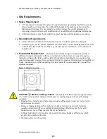
Figure 3: Vibration warning
CAUTION 2 : Machine damage hazard
—Improperly installed suspension type machines
can “walk” out of position during extract (
Figure 3
), endangering personnel and damaging
equipment.
• Roughen floor. Install anchor bolts and grout under all base pads to prevent “teeter-totter”
and sideways movement.
• Remove shipping restraints after machine is in place. Failure to remove all restraints
(usually painted red) will cause malfunctions and damage. Restraints may be located
behind access covers. These include, but are not limited to:
• Cylinder hold-down bolts, brackets, straps and/or blocking. Replace all fasteners which
are part of the machine structure.
• Vibration safety switch restraint.
41
Summary of Contents for 48040M7K
Page 2: ......
Page 8: ......
Page 9: ...Safety 1 5 ...
Page 43: ...Installation 2 39 ...
Page 56: ......
Page 57: ...Drive 3 53 ...
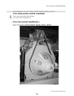
Page 59: ...Drive Components and Belt Installation PELLERIN MILNOR CORPORATION Figure 2 Detailed views 55 ...
Page 93: ...Frame and Tilt 4 89 ...
Page 101: ...Hydraulic Assemblies 5 97 ...
Page 110: ......
Page 111: ...Door Assemblies 6 107 ...
Page 125: ...Water and Steam 7 121 ...
Page 137: ...Chemical 8 133 ...
Page 142: ......
Page 143: ...Control and Sensing Assemblies 9 139 ...
Page 149: ...Dimensional 10 145 ...
Page 150: ......
Page 151: ...147 ...

