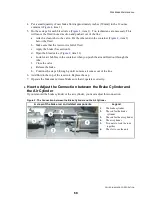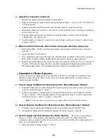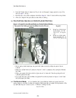
Disk Brake Maintenance
PELLERIN MILNOR CORPORATION
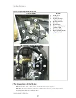
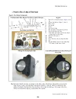
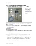
Figure 1: A typical hydraulic brake system
The air cylinder
Legend
The hydraulic cylinder and the caliper
.
1.
Tubing for air
2.
Air cylinder
3.
Caliper body halves
(
Figure 2
, item 2)
4.
Hydraulic reservoir
5.
Rotor disk
6.
Hydraulic inlet
7.
Valves to drain fluid and
bleed the brake
8.
Hydraulic cylinder
9.
Bolts to attach the caliper
(
Figure 2
, item 1)
1.
The Inspection of the Brake
Note 1:
The brakes shown in this document can look different from your equipment.
Note 2:
Do this inspection when the maintenance schedule tells it is necessary. Do this inspection after
you replace friction pads or do a caliper overhaul.
61
Summary of Contents for 48040M7K
Page 2: ......
Page 8: ......
Page 9: ...Safety 1 5 ...
Page 43: ...Installation 2 39 ...
Page 56: ......
Page 57: ...Drive 3 53 ...
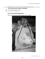
Page 59: ...Drive Components and Belt Installation PELLERIN MILNOR CORPORATION Figure 2 Detailed views 55 ...
Page 93: ...Frame and Tilt 4 89 ...
Page 101: ...Hydraulic Assemblies 5 97 ...
Page 110: ......
Page 111: ...Door Assemblies 6 107 ...
Page 125: ...Water and Steam 7 121 ...
Page 137: ...Chemical 8 133 ...
Page 142: ......
Page 143: ...Control and Sensing Assemblies 9 139 ...
Page 149: ...Dimensional 10 145 ...
Page 150: ......
Page 151: ...147 ...


