Disk Brake Maintenance
PELLERIN MILNOR CORPORATION
5.1.
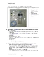
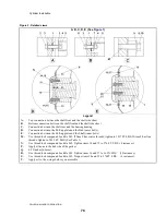
Adjust for maximum rod travel.
1. Operate the master switch to energize control power.
2. Make sure that the air pressure that releases the brake (
Figure 7
, item 1) is 85 -100 PSI ( 5.95
- 07.0 kg/cm-cm).
3. Make sure that the nuts that lock the rods together (
Figure 5
, item 5) are loose.
4. Release the brake (see
Section 6
). Let the air cylinder rod fully retract into the air cylinder as
shown in
Figure 6
, A.
5. Turn the brake rod into the air cylinder rod until the brake rod comes out of the brake
cylinder fully. See
Figure 6
, B.
6. Lock the brake rod (
Figure 5
, item 2) to the air cylinder rod (
Figure 5
, item 3) with two nuts
(
Figure 5
, item 5).
5.2.
Make sure that the brake will continue to operate while the pads wear.
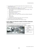
1. Release the brake. On the view slot, put a mark at the position of the lock nuts. (
Figure 6
,
item M1).
2. Apply the brake. See
Section 6
.
3. Put a mark at the position of the lock nuts when the brake is applied. This can be at position
M2a, M2b, or between M2a and M2b. When the pads wear this position will move.
4. Make sure that the distance the rod moves when you apply the brake is 0.75 to 1.0 inches (19-
25 mm). If the travel is more than this, the brake piston can hit the mechanical stop before
the brake engages fully. This condition is shown in
Figure 6
, E (dimension TT).
6.
Operation of Brake Systems
Look at the electrical schematics of your machine to find how your brake is controlled. Some
machines release the brake when you close the door. Some machines have a control relay to
release or apply the brake.
6.1.
How to Apply the Brake for Machines with a "Break Release" Output
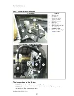
1. Turn the "brake release" control output off to de-energize the air valve to remove air pressure
to the air cylinder (
Figure 1
, item 1).
2. With no air pressure, a spring in the air cylinder will apply force to the hydraulic cylinder
(
Figure 1
, item 8). This will apply pressure to the brake pads (
Figure 2
, item 4) against the
rotor disk (
Figure 1
, item 5). (
Figure 6
, item C,D)
Note 6:
If electrical power or compressed air is missing, hydraulic pressure will apply the brake.
6.2.
How to Release the Brake for Machines with a "Brake Release" Output
1. Turn the control output called "brake release" on to energize the air cylinder valve.
2. Air pressure compresses the spring and releases the brake. (
Figure 6
, item B)
6.3.
How to Apply and then Release the Brake Quickly
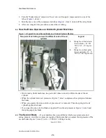
—There are two air tubes at
(
Figure 1
, item 1). One supplies compressed air from an air valve. The other sends this
compressed air to a pressure switch. If you remove one of the two tubes when compressed air is
there, you will apply the brake.
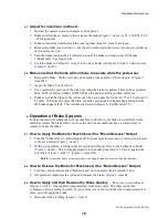
1. Disconnect the air tubing (
Figure 1
, item 1).
70
Summary of Contents for 48040M7K
Page 2: ......
Page 8: ......
Page 9: ...Safety 1 5 ...
Page 43: ...Installation 2 39 ...
Page 56: ......
Page 57: ...Drive 3 53 ...
Page 59: ...Drive Components and Belt Installation PELLERIN MILNOR CORPORATION Figure 2 Detailed views 55 ...
Page 93: ...Frame and Tilt 4 89 ...
Page 101: ...Hydraulic Assemblies 5 97 ...
Page 110: ......
Page 111: ...Door Assemblies 6 107 ...
Page 125: ...Water and Steam 7 121 ...
Page 137: ...Chemical 8 133 ...
Page 142: ......
Page 143: ...Control and Sensing Assemblies 9 139 ...
Page 149: ...Dimensional 10 145 ...
Page 150: ......
Page 151: ...147 ...

