Cylinder Installation
PELLERIN MILNOR CORPORATION
BIIFLM07 (Published) Book specs- Dates: 20160113 / 20160113 / 20160113 Lang: ENG01 Applic: IFL IH4
Cylinder Installation
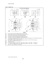
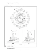
Figure 1: Shell and Cylinder
Cross Section
Legend
A.
Detailed view—Top connection between the shell front and the shell side sheet
B.
Detailed view—Bottom connection between the shell front and the shell side sheet
C.
Detailed view—Connection between the shell rear and the bearing housing
D.
Detailed view—Connection between the Pull-up plate and the Hub (outer bolts)
E.
Detailed view—Connection between the Pull-up plate and the Shaft (inner bolts)
G.
Cylinder
H.
Shell
J.
Shell front
K.
Bearing housing
L.
This dimension must be in this range: 0.3125 inches [8mm] — 0.375 inches [9.5mm].
.
77
Summary of Contents for 48040M7K
Page 2: ......
Page 8: ......
Page 9: ...Safety 1 5 ...
Page 43: ...Installation 2 39 ...
Page 56: ......
Page 57: ...Drive 3 53 ...
Page 59: ...Drive Components and Belt Installation PELLERIN MILNOR CORPORATION Figure 2 Detailed views 55 ...
Page 93: ...Frame and Tilt 4 89 ...
Page 101: ...Hydraulic Assemblies 5 97 ...
Page 110: ......
Page 111: ...Door Assemblies 6 107 ...
Page 125: ...Water and Steam 7 121 ...
Page 137: ...Chemical 8 133 ...
Page 142: ......
Page 143: ...Control and Sensing Assemblies 9 139 ...
Page 149: ...Dimensional 10 145 ...
Page 150: ......
Page 151: ...147 ...

