Ê
Replacing the Bearing Housing, Seal Sleeve,
and Seals (Front or Rear)
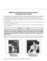
1. With the seal sleeve removed, press all old seals out of the bearing housing. Remove the large o-ring from the
outside of the housing. Thoroughly clean the bearing housing and flush out all grease passages to make cer-
tain they are unblocked. Remove the o-rings from the inside of the seal sleeve and clean the seal sleeve.
2. While the bearing housing is dissassembled, charge all grease passages with grease. This will assure that there
are no blockages.
3. Replace the o-rings in the seal sleeve and the large o-ring on the outside of the bearing housing. Replace with
new o-rings if the old ones are worn.
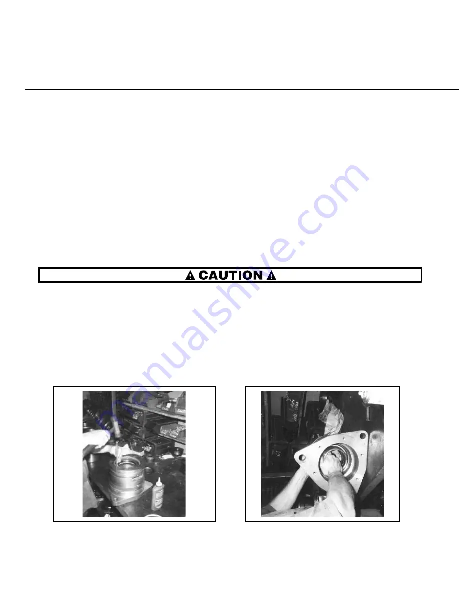
4. Press new seals into the bearing housing. You may gently work the seals in with a mallet and metal drift as
shown in FIGURE 5.
Each seal must be of the proper material and face the proper direction. The type of material
and direction the seal faces may differ from one seal to another within the same bearing
housing and also from one type of machine to another. It is essential to consult the Main
Bearing Assembly drawing for your machine for the proper part number and direction to
face each seal.
5. Slip the seal sleeve into the bearing housing as shown in FIGURE 6 below right, using care not to damage or
fold under any of the seal lips. Be sure to insert the sleeve in the proper direction (see Bearing Assembly draw-
ing).
NOTE: If both housings are being installed, install the rear housing first.
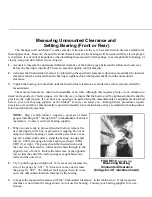
6. With two of the three temporary guide rods in position on the shell, place the bearing housing onto the guide
rods and install the seal sleeve setting fixture on to the bearing housing as shown in FIGURE 7. The seal
sleeve setting fixture prevents the seal sleeve from being pushed out of the housing as the housing is in-
serted into the shell. Note that the seal sleeve setting fixture and the bearing setting fixture are very similar,
but the seal sleeve setting fixture has a longer hub.
7. With a clean, lint free cloth, apply a coating of light machine oil to the outside of the housing, to assist in in-
stallation. Push the housing into the shell as shown in FIGURE 8. Once the housing is far enough into the
shell to support itself, place any shims back into position between the housing and the shell. Remove, then
replace guide rods if required to place shims under bearing housing pads.
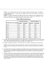
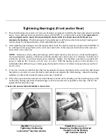
8. Install the third guide rod, spacers if required, and hex-
nuts, using these to seat the housing fully, as shown
in FIGURE 9. Remove the seal sleeve setting fix-
ture.
9. Remove the guide rods and install the bearing housing
cap bolts. See “BOLT TORQUE REQUIRE-
MENTS” elsewhere, for proper torques.
10. With the grease gun, pump grease into the inner por-
tion of the bearing cavity, such that when the bear-
ing is installed, the space between the bearing and
the seals will be approximately 1/3 full of grease.
11 Proceed to “Measuring Unmounted Clearance . . .”
below, even if both the front and rear bearings are
being replaced. Once the rear bearing is installed,
the bearing housing replacement procedures may
then be repeated for the front (soil side) bearing hous-
ing.
Î
FIGURE 5
(MSSM0303AE)
Î
Installing Seals in
Bearing Housing
Î
FIGURE 6
(MSSM0303AE)
Î
Installing Seal Sleeve in
Bearing Housing
Î
FIGURE 7
(MSSM0303AE)
Î
Installing the Bearing Housing Setting
Fixture onto Housing (42" machine shown)
Î
FIGURE 8
(MSSM0303AE)
Î
Pushing the Bearing Housing into the
Shell (60" Rapid-load machine shown)
Î
FIGURE 9
(MSSM0303AE)
Î
Tightening the Bearing Housing
into the Shell (42" machine shown)


