background image

26

Pellerin Milnor Corporation

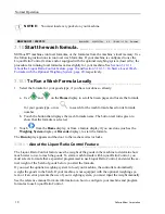
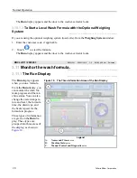
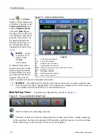
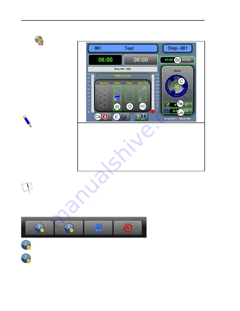
Figure 16.

Formula Control Areas

Legend

C.

Cylinder speed controls

Ca.

Cancel the formula

D.

Drain and reuse controls

E.

End formula intervention

H/C.

Heat and cool (steam and cooldown) controls

Lw.

Bath level controls

St.

Step timer controls

Tw.

Bath temperature controls

W.

Water valve controls

Touch

on the

Run

display to start formula in-
tervention. Controls in the

Names and Timers

area

and the

Machine Status

area of the

Run

display

become active so that you
can change the formula in
progress. Green boxes on
the display identify the
formula control areas, or
the settings that can be
changed, as shown in

Fig-

ure 16

.

NOTE:

A pass-

word may be re-
quired to use
formula
intervention.

In formula intervention
mode, touch a box to dis-
play the pop-up controls
for that setting. The pop-
up controls available cor-
respond with your ma-
chine’s equipment and your configuration decisions.

NOTICE:

The MilTouch™ controller prevents the activation of certain controls when

their activation would be inappropriate. For example, the controls for the water valves are
not available when the bath water is at its maximum level.

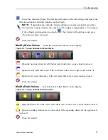
Modify Step Timer

— Touch the box identified by item St on

Figure 16

.

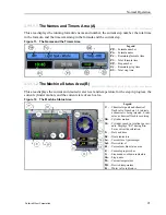
Figure 17.

Pop-up Controls for Step Timer

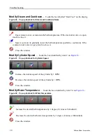
Add 1 minute to the remaining step time.

Subtract 1 minute from the remaining step time. If there is less than 1 minute remaining

on the step timer, the timer is reduced to 00:00 and the controller moves on to the next phase
in the current step, or the next step if there are no more phases.

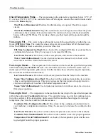
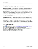
Troubleshooting

Summary of Contents for MilTouch MWB26Z

Page 1: ...PELLERIN MILNOR CORPORATION Post Office Box 400 Kenner Louisiana 70063 0400 U S A Operator Guide Side loaded Barrier MilTouch Washer extractor Manual Number MKCLKO01 Edition ECN 2021172 ...

Page 2: ......
Page 3: ...3 7 Close the inner door 15 3 8 Close the outer door 15 3 9 Align and load the second pocket or the second and third pockets 15 3 9 1 To Load the Pocket s with a Weighing System 16 3 9 2 To Load the Pocket s with a Separate Laundry Scale 17 3 10 Start the wash formula 18 3 10 1 To Run a Wash Formula Locally 18 3 10 1 1 About the Liquor Ratio Control Feature 18 3 10 1 2 To Start a Local Wash Formul...

Page 4: ...rmation Areas of the Run Display 20 Figure 11 The Names and the Timers Area 21 Figure 12 The Machine Status Area 21 Figure 13 Chemicals from Valves 1 and 2 Injecting 22 Figure 14 Standard Controls 22 Figure 15 Chemical Injection Dialog Box 25 Figure 16 Formula Control Areas 26 Figure 17 Pop up Controls for Step Timer 26 Figure 18 Pop up Controls for Water Valves 27 Figure 19 Pop up Controls for Dr...

Page 5: ...olved in the commissioning programming and servicing of the machine WARNING Careless use can cause death or serious injury and property damage Read the machine manuals before you install operate service or clean the machine Do not attempt to service the machine or reach into normally guarded areas unless you are a qualified service technician This MilTouch industrial washer extractor has one or mo...

Page 6: ...trols on the MilTouch touchscreen control all machine functions needed on the soil side of the machine see Section 2 3 How to Use the MilTouch Controller page 7 The buttons on the control panel shown in Figure 1 con trol all machine functions needed on the clean side of the machine Figure 1 Clean Side Control Panel Legend A Emergency stop switch B Clean side buzzer H2 C Clean side light H3 D Repos...

Page 7: ...tions Flush Button Optional Figure 2 Flush Button This optional button rinses the detergent box with cold water to manually flush dry chemicals into the machine This button can also be used to fill the machine with cold water to increase the water level in the machine Heating Switch Optional Figure 3 Heating Switch This button selects the type of heating on machines with option al combined heating...

Page 8: ...igure 1 rotates the drum cylinder to the soil side position BNVLUO01 2018513 BNVLUO01 0000189558 B 4 1 2 20 2 17 PM Released 2 2 Emergency Stop Switch locking push button BNVLUO01 C01 0000189557 E 3 B 4 F 2 12 9 20 9 19 AM Released One or more emergency stop switches pictured below may be provided on the device When pressed any emergency stop switch removes power from the machine controls stops th...

Page 9: ... a finger to touch the glass Do not touch the screen with a tool Turn the master switch on to apply power to the control system The Home display appears on the touchscreen 2 3 1 The Home Display BNCLJO09 C01 0000211248 E 3 D 4 D 2 12 9 20 4 22 PM Released The display pictured in the following figure subsequently referred to as the Home display is used to access all the other displays Buttons label...

Page 10: ...e display 2 3 2 About the Start Button BNCLJO10 C02 0000336421 E 3 D 4 A 5 3 5 21 10 37 AM Released On machines without any optional features the selected formula immediately starts when you press the start button on the Home display If your machine has optional features such as a barcode scanner load cells or liquor ratio con trol the displays that allow you to use these features ex the Barcode d...

Page 11: ...y and the allied non Mil nor equipment you use such as laundry carts sling systems chemicals and chemical systems Milnor advises you to obtain and read the safety literature provided for your facility and for all equipment you use Examples of possible risks related to the type of laundry facility or to allied equipment are goods handling sharp objects such as scalpels and syringes left in OR gowns...

Page 12: ...ur Milnor dealer worked with your laundry personnel to determine the optimum machine for your needs This took into account factors such as the types of goods to be washed and the expected soil content of the goods which can cause the correct load size to vary greatly among goods types For example the more bulky the goods the smaller the permissible load size The correct load sizes will be what was...

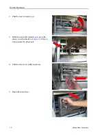
Page 13: ... to unlock the door The controller locks both of the outer doors during normal operation and automatically unlocks them when the machine is ready to receive a load and when the machine is ready to discharge When the outer door is unlocked hold the handle at the bottom of the door and lift it to open the door 3 5 Open the inner door BNWVUO01 T01 0000254597 E 3 C 7 C 4 9 2 20 5 10 PM Released If you...

Page 14: ...tion 2 Pull the lever towards you 3 With the lever still towards you press the safety switch item D in Figure 6 This ac tion releases the door lock 4 Pull the lever to its fullest position 5 Open the inner door Normal Operation ...

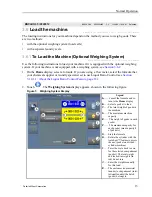
Page 15: ... formula that your chemical supplier or laundry specialist set to use Liquor Ratio Control see Section 3 10 1 1 About the Liquor Ratio Control Feature page 18 2 Touch The Weighing System display appears shown in the following figure Figure 7 Weighing System Display Legend A Cancel the formula and re turn to the Home display B Select a pocket to load C The total weight of goods in the machine D The...

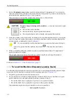
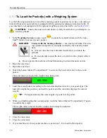
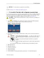
Page 16: ...3 remove the goods from the machine then touch This tares the scale back to zero 5 When you finish loading the cylinder or pocket touch the button labeled Compartment 1 again to confirm the weight The weight value turns red as shown below and the weight can no longer be adjusted Continue to Section 3 7 Close the inner door page 15 3 6 2 To Load the Machine Separate Laundry Scale BNCLKO05 T01 00002...

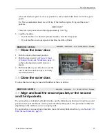
Page 17: ...nism page 11 to the locked position until it clicks as shown 3 Pull the handle in your direction to test the lock If the door does not open it is fully closed and locked 3 8 Close the outer door BNWUUO04 T02 0000289837 E 3 A 18 A 12 9 22 20 11 42 AM Released To close the door swing it closed with sufficient force to latch it BNWVUO05 2020512 BNWVUO05 0000289691 C 2 12 14 20 12 01 PM Released 3 9 A...

Page 18: ...lways close the inner and outer doors before you rotate the cylinder Do not attempt to open the door or reach into the cylinder while it rotates Do not operate the machine with malfunctioning two hand manual controls 2 Open the outer door 3 Open the inner door 4 Touch the button labeled Compartment 2 to activate the load cell scale in the second pocket The scale tares to zero and the weight value ...

Page 19: ...reen A dialogue box appears shown in the following figure which prompts you to transfer control to the clean side or the soil side Figure 8 Confirmation Dialogue Box 2 Touch the button labeled Soil The basket rotates so that you can access the next pocket on the soil side DANGER Contact with the turning cylinder can crush your limbs The turn ing cylinder and goods are normally isolated by the lock...

Page 20: ...e wash formula based on its formula number b Touch the button that displays the wash formula name The button text turns green to show that the formula is selected 2 Touch from the Home display or from a feature display if you used one such as the Weighing System display or Barcode display to start the formula The Run display appears and the door to the washer extractor locks 3 10 1 1 About the Liq...

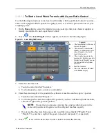
Page 21: ...gs to C The weight of goods in the machine divided into pockets Weight 2 and Weight 3 are on ly used on divided cylinder machines D Start the formula E Close the window and return to the Home display 3 Enter the customer code a Touch the value labelled Customer b Use the keypad to enter a customer code number 4 Enter the actual weight of the goods in the cylinder A machine can have up to 3 pockets...

Page 22: ...r the wash formula BNCLJO11 C01 0000212818 E 3 C 5 C 4 9 11 20 10 27 AM Released 3 11 1 The Run Display BNCLJO11 C02 0000213317 E 3 C 5 C 2 9 11 20 10 28 AM Released Figure 10 The Three Information Areas of the Run Display Legend A Names and Timers area B Machine Status area C Manual Control and Diagnostics area The Run display appears when you run a formula From the Run display you can monitor th...

Page 23: ...C 5 F 2 9 11 20 10 31 AM Released This area displays the current and desired water level and temperature for the step in progress the current cylinder motion and the current state of each valve Figure 12 The Machine Status Area Legend C Chemical signals and chemical flush valve Numbers 1 8 indicate a chemical is being injected F indi cates a chemical flush is occurring Cm Cylinder motion Cs Cylind...

Page 24: ...erence manual 3 11 2 Respond to the end of the cycle BNWBUO02 T01 0000279617 E 3 C 5 A 7 9 11 20 10 37 AM Released The operator signal will sound when the cycle ends BNWBUO04 2020403 BNWBUO04 0000279926 A 12 9 29 20 10 03 AM Released 3 12 Unload the machine BNCLKO05 T02 0000254489 E 3 A 12 C 5 9 9 20 4 39 PM Released While the clean side buzzer sounds the cylinder automatically turns to the clean ...

Page 25: ...s the next pocket 7 Repeat Steps 1 6 until you unload each pocket 8 When you have unloaded all the pockets close the inner door and the outer door 9 Press the Control on Soil Side button to rotate the drum cylinder to the soil side position The outer door on the clean side automatically locks The green light on the soil side illuminates when the machine is ready to receive a new load Normal Operat...

Page 26: ...lled for by the formula The only intervention normally required is to ensure that the chemical containers that supply the chemicals to the system remain at a safe level Optional 5 compartment supply injector a system in which the operator places a measured amount of chemical in each compartment before the start of each wash cycle Each compart ment is dedicated to a type of chemical detergent bleac...

Page 27: ...wash formula in production while it runs You can adjust the step timer water valves drain and reuse valves steam and cooldown controls cylinder speed bath temperature and level The changes you make while in formula intervention mode do not alter the programming of the formula the step decisions Formulas proceed normally in formula intervention mode aside from the changes you make Chemical supplier...

Page 28: ...uired to use formula intervention In formula intervention mode touch a box to dis play the pop up controls for that setting The pop up controls available cor respond with your ma chine s equipment and your configuration decisions NOTICE The MilTouch controller prevents the activation of certain controls when their activation would be inappropriate For example the controls for the water valves are ...

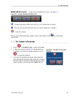
Page 29: ... Touch the box labeled Water on the display Figure 18 Pop up Controls for Water Valves Open the hot water inlet valve If the hot water inlet valve is open touch to close it Open the cold water inlet valve If the cold water inlet valve is open touch to close it Open the 3rd water inlet valve If the 3rd water inlet valve is open touch to close it Close the window Modify Drain Valves Touch the box la...

Page 30: ...n touch to close it Close the window Modify Cylinder Speed Touch the box identified by item C on Figure 16 Figure 21 Pop up Controls for Cylinder Speed Increase the rotation speed of the cylinder by 1 RPM Decrease the rotation speed of the cylinder by 1 RPM Close the window Modify Water Temperature Touch the box identified by item Tw on Figure 16 Figure 22 Pop up Controls for Water Temperature Inc...

Page 31: ...ula touch to end formula intervention 4 1 4 To Cancel a Formula BNCLJB01 T01 0000204083 E 3 C 3 9 11 20 12 09 PM Released 1 Touch on the Run display to cancel a formula Figure 24 Resume or Cancel the Formula 2 A dialog box appears Figure 24 that prompts you to confirm your decision On the dialog box touch to cancel the formula 3 The controller disables all outputs drains the bath water through the...

Page 32: ...and an error code dia log box Figure 25 appears on the Run display See the next section for a list of all the error codes and the possi ble causes solutions 4 2 1 MilTouch Error Messages for Barrier Washer extractors BNCLKT05 R01 0000251061 E 3 B 14 B 4 9 8 20 11 49 AM Released The following are error messages the controller can issue possible causes and solutions Opera tion stops and cannot be re...

Page 33: ...turns to the Home display Inverter error The machine controller cannot tell about the specific error See the inverter manual for details The inverter manual was shipped in an electric box on your machine or with the packet of documentation inside the machine cylinder Pressure Switch Error This error occurs if the pressure in the pressure regulator used to lock and unlock the door and actuate the b...

Page 34: ...ied temperature within the configured Steam Error time The controller issues an error but the steam valve re mains open If the temperature probe senses that the machine has reached its target temperature the error clears and the formula resumes Low Steam Pressure Do a check of the steam pressure from the boiler to the machine Steam Time Configured too Short Do a check of the configured steam time ...

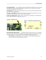
Page 35: ...d Check the tube and remove lint or other obstructions Drain Valve Malfunctioned The drain valve or drain valve solenoid may have malfunctioned Electrical troubleshooting is required see Figure 27 Figure 26 Transducer Tube Figure 27 Schematic of Typical Drain Circuit Serial Communication Failure A peripheral board in the control box has lost communica tion with the processor board The controller s...

Page 36: ...cell Comm Failure This error can occur on machines with the optional weighing sys tem load cells The controller issues this error when it cannot receive data or receives an unex pected data stream from the load cell controller Level Too Low After the machine fills to the configured minimum low water level the controller turns off all outputs and signals this error if the water level drops below ha...

Page 37: ... voltage and or moving parts are present inside the machine when troubleshooting Qualified technicians only Use care to avoid contact with live or moving parts Keep bystanders away 1 Follow the instructions on the Error Causes Solutions display for how to correct the error 2 Touch to return to the Run display 3 In the error code dialog box touch to silence the operator signal close the error code ...

Page 38: ... on instal ling servicing or using Customer Serv ice Technical Support 504 712 7780 504 469 9777 service milnor com www milnor com Customer Service Learn about request or enroll in Milnor service seminars Training 504 712 7716 504 469 9777 training milnor com Determine warranty eligibility or claim status Warranty Administration 504 712 7735 504 469 9777 service milnor com Attention Warranty Ask a...

Reviews: