CUddY^W 4__b 9^dUb\_S[ CgYdSXUc
@5<<5B9> =9<>?B 3?B@?B1D9?>
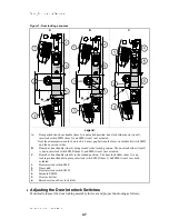
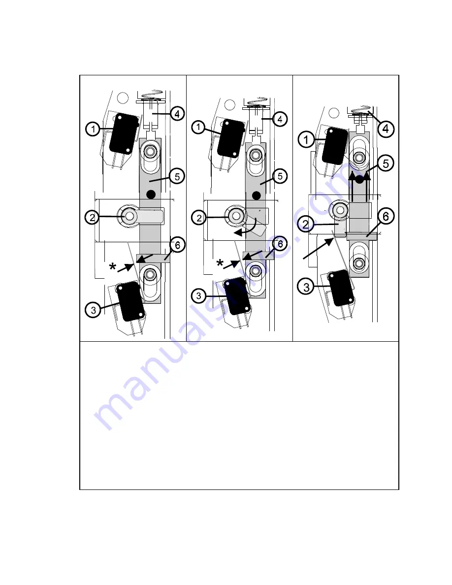
Figure 1: Door locking sequence
A
B
C
Legend
A.
Door pushed shut, door handle (item 2) in unlocked position, door lock slider down (item 5),
interlock switch SMD (item 3) and SME (item 1) not actuated.
Note the minimum sixteenth of an inch (1.6 mm) gap between the lever on interlock switch SMD
and the door lock slider.
B.
Door shut, door handle (item 2) being turned to the locked position. The door lock slider (item 5)
is down, interlock switch SMD (item 3) and SME (item 1) not actuated.
C.
Door shut, door handle (item 2) in the locked position. The door lock slider (item 5) is up,
locking in door handle in place, interlock switch SMD (item 3) and SME (item 1) are both
actuated.
1.
Door interlock switch SME
2.
Door catch
3.
Door interlock switch SMD
4.
Solenoid EMDL
5.
Door lock slider
6.
Raised section of door lock slider
!
0SYdbcX]VcWT3^^a8]cTa[^RZBfXcRWTb
Periodically inspect the door locking assembly for wear and proper functioning as follows:
47
Summary of Contents for MilTouch MWF27Z8 Series
Page 2: ......
Page 23: ...Installation 1 19 ...
Page 39: ...Service and Maintenence 2 35 ...
Page 61: ...Drive Assemblies 3 57 ...
Page 72: ......
Page 73: ...Suspension 4 69 ...
Page 78: ......
Page 79: ...Shell and Door Assemblies 5 75 ...
Page 89: ...Water and Steam Piping and Assemblies 6 85 ...
Page 96: ......
Page 97: ...Chemical Supply Devices 7 93 ...
Page 107: ...Dimensional Drawings 8 103 ...
Page 108: ......
Page 109: ...105 ...
Page 110: ...106 ...

