background image

Pellerin Milnor Corporation

Trademarks

BNUUUU02.R01 0000158093 A.2 7/13/17 1:11 PM Released

These words are trademarks of Pellerin Milnor Corporation and other entities:

Table 1 Trademarks

AutoSpot™

GreenTurn™

Milnor®

PulseFlow®

CBW®

GreenFlex™

MilMetrix®

PurePulse®

Drynet™

Hydro-cushion™

MilTouch™

Ram Command™

E-P Express®

Linear Costa Master™

MilTouch-EX™

RecircONE®

E-P OneTouch®

Linear Costo™

Miltrac™

RinSave®

E-P Plus®

Mentor®

MultiTrac™

SmoothCoil™

Gear Guardian®

Mildata®

PBW™

Staph Guard®

End of document: BNUUUU02

BNUUUU02 / 2017285A

BNUUUU02

0000158094

A.3

7/13/17 1:53 PM

Released

3

Summary of Contents for MilTouch MWF27Z8 Series

Page 1: ... MPIMWF27AE 2019506A Publishing System TPAS2 Access date 12 13 2019 Document ECNs Latest Installation and Service MWF27J8 MWF27Z8 Washer Extractors PELLERIN MILNOR CORPORATION POST OFFICE BOX 400 KENNER LOUISIANA 70063 0400 U S A ...

Page 2: ......

Page 3: ...tion BIMUUI01 20030213 30 Shipping Brackets BMP160003 2016092A 32 Covers BMP130050 2018383A 35 2 Service and Maintenence 36 Service Connections BNWBUI02 2018392A 41 Servicing the Door to Open it with Power Off or with a Malfunctioning Door Lock BIRH3M02 20080731 46 Setting Door Interlock Switches BIRH3M01 20030214 49 Torque Requirements for Fasteners BIUUUM04 20180109 57 3 Drive Assemblies 58 Driv...

Page 4: ...al Supply Devices 94 Soap Chute BMP130062 2013484A 96 Peristaltic Supply BMP130063 2013484A 99 5 Compartment Supply BMP130064 2013484A 103 8 Dimensional Drawings 105 Dimensional Drawing MWF27J8 MWF27Z8 BDMWF27JAE 2019495D 106 Dimensional Drawing MWF27F J W Options BDMWF27JAB 2019495D ...

Page 5: ...ical attack are not covered by this warranty For parts which require routine replacement due to normal wear such as gaskets contact points brake and clutch linings belts hoses and similar parts the warranty time period is 90 days We reserve the right to make changes in the design and or construction of our equipment including purchased components without obligation to change any equipment previous...

Page 6: ...ou can also get components from the Milnor factory Tell the supplier the machine model and serial number and this data for each necessary component The component number from this manual The component name if known The necessary quantity The necessary transportation requirements If the component is an electrical component give the schematic number if known If the component is a motor or an electric...

Page 7: ...emarks AutoSpot GreenTurn Milnor PulseFlow CBW GreenFlex MilMetrix PurePulse Drynet Hydro cushion MilTouch Ram Command E P Express Linear Costa Master MilTouch EX RecircONE E P OneTouch Linear Costo Miltrac RinSave E P Plus Mentor MultiTrac SmoothCoil Gear Guardian Mildata PBW Staph Guard End of document BNUUUU02 BNUUUU02 2017285A BNUUUU02 0000158094 A 3 7 13 17 1 53 PM Released 3 ...

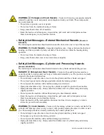
Page 8: ...icted to those employees given the task of using it only specifically designated workers carry out repairs modifications maintenance or servicing information instruction and training is provided workers and or their representatives are consulted Work equipment must comply with the requirements listed below The owner user must verify that installation and maintenance of equipment is performed in su...

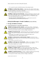
Page 9: ...zards is provided on the machine safety placards in the Safety Guide and throughout the other machine manuals Placards must be kept clean so that the information is not obscured They must be replaced immediately if lost or damaged The Safety Guide and other machine manuals must be available at all times to the appropriate personnel See the machine service manual for safety placard part numbers Con...

Page 10: ...y or limbs and dismember you The goods are normally isolated by the locked cylinder door Do not attempt to open the door or reach into the cylinder until the cylinder is stopped Do not touch goods inside or hanging partially outside the turning cylinder Do not operate the machine with a malfunctioning door interlock Open pocket machines only Do not jog the cylinder and pull the goods at the same t...

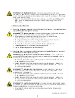
Page 11: ...er is turning and or starting the cycle with the door open exposing the turning cylinder Do not operate the machine with any evidence of damage or malfunction WARNING 9 Multiple Hazards Operating the machine with an inoperative safety device can kill or injure personnel damage or destroy the machine damage property and or void the warranty Do not tamper with or disable any safety device or operate...

Page 12: ...icing Hazards Vital Information for Service Personnel see also service hazards throughout manuals WARNING 16 Electrocution and Electrical Burn Hazards Contact with electric power can kill or seriously injure you Electric power is present inside the cabinetry unless the main machine power disconnect is off Do not service the machine unless qualified and authorized You must clearly understand the ha...

Page 13: ...Safety Suspended Open Pocket Non tilting Washer Extractors PELLERIN MILNOR CORPORATION End of BIUUUS27 9 ...

Page 14: ...appears on most tags The machine ships with safety operator and routine maintenance guides for customer use Milnor dealer manuals for installing commissioning and servicing the machine are also available from the Milnor Parts department B2TAG88005 This carefully built product was tested and in spected to meet Milnor performance and quality standards by identification mark of tester B2TAG94081 Moto...

Page 15: ... start the machine until these actions are completed B2T2002013 Do not start the machine until shipping restraints are removed This tag will appear on the outside of the machine to alert you to the presence of internal shipping restraints A tag will also appear on the restraint to help identify it Most but not all shipping restraints display the color red Some shipping restraints are also safety s...

Page 16: ...hine Eliminate water hammer on the water lines to this machine Water hammer can rupture the water inlet valves on this machine Follow applicable codes when installing water hammer arresters Maintain incoming water pressure between 10 and 75 psi between 0 7 and 5 1 bar Pressures outside this range can damage the water valves in this machine End of document BNWMAI01 Installation Tag Guidelines 12 ...

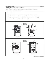
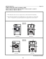
Page 17: ...t read it replace the placard immediately If the placard is aluminum the mounting holes are on the machine Use self tapping screws If the placard is vinyl put the placard in the approximate location shown Front View Front View Rear View Rear View Page 1 3 MWF27J8 MWF27Z8 MWF45J8 MWF45Z8 MWF63J7 MWF63Z7 MWF77J7 MWF77Z7 MWF63C7 MWF63Y7 MWF77C7 MWF77Y7 Safety Placards and Locations 4 4 13 ...

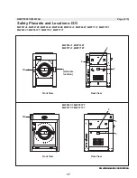
Page 18: ...MWF27Z8 MWF45J8 MWF45Z8 MWF63J7 MWF63Z7 MWF77J7 MWF77Z7 MWF63C7 MWF63Y7 MWF77C7 MWF77Y7 PELLERIN MILNOR CORPORATION 3 Front View Rear View Safety Placards and Locations Page 2 3 BMP130066 2018376A 1 2 3 MWF63 7 MWF63 7 C Y MWF77C7 MWF77Y7 Front View Rear View 4 4 alternate location 14 ...

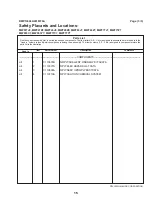
Page 19: ...embly The item numbers 1 2 3 etc assigned to components relate the parts list to the illustration Parts List PELLERIN MILNOR CORPORATION Page 3 3 COMPONENTS all 1 01 10631B NMPLT SHELLFNT WARN MWF TACATA all 2 01 10377A NPLT ELEC HAZARD LG TCATA all 3 01 10699A NPLT SERV HZRD PLYEST TCATA all 4 01 10710A NPLT CAUTION CHEMICAL SYSTEM MWF27J8 MWF27Z8 MWF45J8 MWF45Z8 MWF63J7 MWF63Z7 MWF77J7 MWF77Z7 M...

Page 20: ... MWF63Y7 MWF77C7 MWF77Y7 Safety Placards and Locations ISO If the placard is removed or you cannot read it replace the placard immediately If the placard is aluminum the mounting holes are on the machine Use self tapping screws If the placard is vinyl put the placard in the approximate location shown Front View Front View Rear View Rear View BMP150057 2018376A 1 2 3 3 16 ...

Page 21: ...77C7 MWF77Y7 Front View Rear View MWF27J8 MWF27Z8 MWF45J8 MWF45Z8 MWF63J7 MWF63Z7 MWF77J7 MWF77Z7 MWF63C7 MWF63Y7 MWF77C7 MWF77Y7 Page x x PELLERIN MILNOR CORPORATION PELLERIN MILNOR CORPORATION Front View Rear View Safety Placards and Locations ISO 1 alternate location Page 2 3 3 BMP150057 2018376A 17 ...

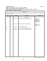
Page 22: ... column to identify which components belong to an assembly The item numbers 1 2 3 etc assigned to components relate the parts list to the illustration Parts List PELLERIN MILNOR CORPORATION Page 3 3 COMPONENTS A 1 01 10631Y NPLT SHELL FRT WARN NOTILT ISO NON TILT MWF27J8 Z8 MWF45J8Z8 MWF63J7 Z7 MWF77J7 Z7 B 1 01 10631Z NPLT SHELL MWF FRT WARN ISO TILT MWF63C7 Y7 MWF77C7 Y7 all 2 01 10377 NPLTE WAR...

Page 23: ...Installation 1 19 ...

Page 24: ...ty to safely withstand our published forces without transmitting undue vibration If the subsoil has subsided or if the floor slab itself has insufficient strength and rigidity a deeper foundation poured as to become monolithic with the floor slab may be required Support pilings may even be required if the subsoil itself is springy i e if its resonant frequency is near the operating speed of the ma...

Page 25: ...r structural engineer must be engaged for this purpose Figure 1 How Rotating Forces Act on the Foundation Typical Machine Legend A Direction of force B Load C Rotation Frequency RPM 60 Figure 1 above is intended to depict both on grade and above grade installations and is equally applicable to flexibly mounted washer extractors as well as to rigid models installed either directly on a floor slab o...

Page 26: ... Chemical Supplies and Wash Formulas Some examples that can cause damage are a very high concentration of chlorine bleach a mixture of acid sour and hypo chlorite chemical supplies examples chlorine bleach hydrofluosilicic acid that stay on the stainless steel because they are not quickly flushed with water The book Textile Laundering Technology by Charles L Riggs gives data about correct chemi ca...

Page 27: ...Let the Chemical Supply Go In the Machine by a Siphon Schematic Views Legend P Pump T Chemical tank S The siphon occurs above here Liquid in the gray parts of the chemical tube and tank can go in the machine Prevent Damage from Chemical Supplies and Chemical Systems 23 ...

Page 28: ...ct Configurations That Let the Chemical Supply Go In the Machine by Gravity Schematic Views Legend P Pump T Chemical tank D Chemical tube Liquid in the gray areas can go in the machine Prevent Damage from Chemical Supplies and Chemical Systems 24 ...

Page 29: ...the chemical manifold supplied There is a manifold on the machine to at tach chemical tubes from a chemical pump system The manifold has a source of water to flush the chemical supplies with water Figure 3 Examples of Manifolds for Chemical Tubes Your equipment can look different Prevent Damage from Chemical Supplies and Chemical Systems 25 ...

Page 30: ... the chemical tube fully below the inlet It is also necessary that there is no pressure in the chemical tube or tank when the system is off Figure 4 A Configuration that Prevents Flow in the Machine When the Pump is Off if the chemical tube and tank have no pressure Schematic View Legend I Chemical inlet on the machine L Chemical tube P Pump T Chemical tank Prevent leaks When you do maintenance on...

Page 31: ...at protrude from the machine frame shell front door electric boxes controls guards conduits conveyors piping valves drains vents tilt frames etc 3 Do not pull on door conduit to help move the machine as the door switch may require readjustment BXcT AT dXaT T cb B_PRT AT dXaT T c 1 All openings and corridors through which equipment must pass during installation must be large enough to accommodate t...

Page 32: ... skids Observing all precautions lift the machine off its skids and lower the machine onto blocking Shim the blocking until the machine is level and approximately l 25 clearance exists under each base pad Install anchor bolts as shown on the dimensional drawing but do not tighten bolts until grout is completely dry 2 Apply grout between the existing foundation floor and the base pads observing the...

Page 33: ...d DO NOT remove shipping restraints until installation is complete DO remove all shipping restraints before operating machine Prior to operation Remove the red locking bolts from the front and back of the shell Remove the red shipping bracket stands Remove the tie wrap that secures the vibration safety switch Check the perforated cylinder for smoothness before placing machine in service Milnor can...

Page 34: ...NOR CORPORATION BMP160003 2016092A Shipping Brackets Before operating remove the shipping brackets painted red The shipping brackets may be retained in the event the machine must be moved See BIMUUI01 2 3 4 2 3 4 1 Typical 4 Places MWF27J8 MWF27Z8 30 ...

Page 35: ...hich components belong to an assembly The item numbers 1 2 3 etc assigned to components relate the parts list to the illustration Parts List Shipping Brackets PELLERIN MILNOR CORPORATION Page 2 2 COMPONENTS all 1 98MW02936W SHIPPING BRACKET MWF27 all 2 98CX770147 HEXCAPSCRM12X30 ZINC8 8 all 3 98CX773113 HEXNUTM12 ZINC all 4 98CX773513 FLATWASHER D12 ZINC BMP160003 2016092A Shipping Brackets MWF27J...

Page 36: ...Page 1 2 BMP130050 2018383A Covers MWF27J8 MWF27Z8 PELLERIN MILNOR CORPORATION PELLERIN MILNOR CORPORATION 1 2 All covers are the same color as the frame Pre production model shown 32 ...

Page 37: ...Page 2 3 PELLERIN MILNOR CORPORATION PELLERIN MILNOR CORPORATION 1 3 4 Typical BMP130050 2018383A Covers MWF27J8 MWF27Z8 33 ...

Page 38: ... In column to identify which components belong to an assembly The item numbers 1 2 3 etc assigned to components relate the parts list to the illustration Parts List Covers PELLERIN MILNOR CORPORATION Page 3 3 BMP130050 2018383A Covers COMPONENTS all 1 98MW02915 COVER SIDE MWF27 all 2 98MW02933 COVER TOP MWF27 all 3 98MW02916 COVER REAR MWF27 all 4 98CX902470 KEY LOCK MWF27J8 MWF27Z8 34 ...

Page 39: ...Service and Maintenence 2 35 ...

Page 40: ...nch when connecting plumbing 1 Inlet pressures must be within the minimum maximum range specified Pressure outside of the specified range may cause the machine to operate inefficiently or malfunction and may damage machine components 2 A separate flush water valve pressure regulator set for approximately 28 psi 193 kPa is shipped with the machine Figure 1 Flush water valve pressure regulator page ...

Page 41: ...ts Connection Description Destination Requirements or Description Piping Specifications Drain 3 pipe socket joint unrestricted gravity feed to sewer external back pressure may extend wash times Do not reduce Rubber hose PVC or other approved materi al per plumbing code Vent 3 3 Power Connections and Precautions BNWBUI01 C04 0000204322 A 3 9 21 18 2 37 PM Released WARNING Electrocution and Electric...

Page 42: ...ilar lag fuses the nameplate fuse sizes must not be applied to standard fuses 4 Stinger leg if any must be connected to terminal L3 never to terminals L1 or L2 5 Make power and liquid supply electrical connections within junction boxes on the rear of the machine 6 Verify motor rotation Figure 2 Correct Rotation During Drain and Extract when view ing front of machine page 3 See the operating and tr...

Page 43: ...A 3 A 2 9 20 18 4 18 PM Released Remove all shipping restraints usually marked in red Restraints may be located behind access panels Restraints may include the vibration switch restraint Figure 4 Typical Vibration Switch Showing Restraint in Place page 4 Figure 4 Typical Vibration Switch Showing Restraint in Place Service Connections 39 ...

Page 44: ...e BNWBUI01 C06 0000204319 A 3 A 2 9 20 18 4 18 PM Released Check the perforated cylinder for smoothness Milnor will not accept responsibility for the cyl inder finish after the machine is placed in service End of document BNWBUI02 Service Connections 40 ...

Page 45: ...ng machine operation before returning the machine to normal service 1 Disassembly 1 1 Removing the Handle and Opening the Door The handle is held in place on the shaft with a thrust washer and retaining clip in front of the handle and a flange bearing and retaining clip behind the handle The amount of turning force the handle can exert on the shaft is adjustable with the four set screws springs an...

Page 46: ... in Figure 4 Remove the rear retaining clip Push against the door to release the retaining clip Figure 3 Front Retaining Clip and Thrust Washer Figure 4 Rear Flange Bearing being removed and Retaining Clip arrow Notice 3 Risk of component damage The return spring is located around the shaft between the door and the shaft cam The end of the spring is inserted into a small hole in the shaft cam The ...

Page 47: ... the Door Lock Mechanism Tip It is easier and more reliable to remove the shaft from the door lock mechanism then to attempt to reinsert the shaft into the door and replace the handle while the shaft is still captive in the door lock 1 Remove the cover not shown from the door lock mechanism Figure 6 2 Using a screwdriver push down the door lock slider pin Figure 6 and rotate the shaft Figure 7 cou...

Page 48: ...kwise about 90 degrees until the shaft fully seats into the door When properly seated the shaft finger the latch will align with the key way on the door lock mechanism 4 Install the rear retaining clip on the shaft 5 Slide the door handle and flange bearing onto the shaft 6 Install the front thrust bearing and retaining clip on the shaft 7 Repeat the following sub steps four times once for each ba...

Page 49: ...all four set screws are in place check to be sure the handle will ratchet if turned counterclockwise or if latched with more force than necessary Make 1 4 turn adjustments to all four set screws if necessary to achieve the proper tension 9 Install the black plastic cap over the center of the handle End of BIRH3M02 45 ...

Page 50: ...he illustrations in Figures 1 while reading the following explanation After the door is shut the turning door catch item 2 physically contacts door interlock switch SMD item 3 Actuating this switch tells the microprocessor that the door is closed Note that the door handle is not locked in place and the door can be opened if needed The machine can be programmed but cannot start the wash program or ...

Page 51: ...m 2 being turned to the locked position The door lock slider item 5 is down interlock switch SMD item 3 and SME item 1 not actuated C Door shut door handle item 2 in the locked position The door lock slider item 5 is up locking in door handle in place interlock switch SMD item 3 and SME item 1 are both actuated 1 Door interlock switch SME 2 Door catch 3 Door interlock switch SMD 4 Solenoid EMDL 5 ...

Page 52: ...it stops Check for a minimum of one sixteenth of an inch clearence 1 6 mm between the raised portion of the door slider item 6 and the lever of interlock switch SMD item 3 2 Manually push the door slider assembly up until it stops Check that the rising slider depresses interlock switch SME item 1 making the switch End of BIRH3M01 48 ...

Page 53: ...ASTM A307 and stainless steel B Grade BC ASTM A354 C SAE Grade 5 ASTM A449 D SAE Grade 8 and ASTM A354 BD 1 Torque Values These tables give the standard dimension grade threadlocker and torque requirements for fasteners frequently used on Milnor equipment Note 1 Data from the Pellerin Milnor Corporation Bolt Torque Specification bolt_torque_milnor xls 2002096 1 1 Fasteners Made of Carbon Steel 1 1...

Page 54: ... 569 7 8 x 9 167 226 429 582 606 821 531 719 7 8 x 14 184 249 473 641 668 906 1 x 8 250 339 644 873 909 1232 796 1079 1 x 12 274 371 704 954 994 1348 1 x 14 281 381 723 980 1020 1383 1 1 8 x 7 354 480 794 1077 1287 1745 1126 1527 1 1 8 x 12 397 538 891 1208 1444 1958 1 1 4 x 7 500 678 1120 1519 1817 2464 1590 2155 1 1 4 x 12 553 750 1241 1682 2012 2728 1 3 8 x 6 655 888 1469 1992 2382 3230 2085 28...

Page 55: ...7 266 354 595 807 966 1288 845 1126 1 1 8 x 12 298 404 668 890 1083 1444 1 1 4 x 7 375 500 840 1120 1363 1817 1192 1590 1 1 4 x 12 415 553 930 1261 1509 2013 1 3 8 x 6 491 655 1102 1470 1787 2382 1564 2085 1 3 8 x 12 559 758 1254 1672 2034 2712 1 1 2 x 6 652 870 1462 1982 2371 3161 2075 2767 1 1 2 x 12 733 994 1645 2194 2668 3557 1 1 2 With a Threadlocker Table 5 Threadlocker by the Diameter of th...

Page 56: ...25 34 22 30 5 16 x 24 13 18 19 26 27 37 27 37 3 8 x 16 20 27 31 42 44 60 38 52 3 8 x 24 23 31 35 47 50 68 7 16 x 14 32 43 49 66 70 95 61 83 7 16 x 20 36 49 55 75 78 106 1 2 x 13 49 66 75 102 107 145 93 126 1 2 x 20 55 75 85 115 120 163 9 16 x 12 70 95 109 148 154 209 134 182 9 16 x 18 78 106 121 164 171 232 5 8 x 11 97 132 150 203 212 287 186 252 5 8 x 18 110 149 170 230 240 325 Table 8 Torque Val...

Page 57: ...Apply LocTite 277 Dimension The Grade of the Bolt Grade 2 Grade 5 Grade 8 Grade BC Pound feet N m Pound feet N m Pound feet N m Pound feet N m 1 x 8 325 441 837 1135 1181 1601 1034 1402 1 x 12 356 483 916 1242 1293 1753 1 x 14 365 495 939 1273 1326 1798 1 1 8 x 7 461 625 1032 1399 1674 2270 1464 1985 1 1 8 x 12 516 700 1158 1570 1877 2545 1 1 4 x 7 650 881 1456 1974 2362 3202 2067 2802 1 1 4 x 12 ...

Page 58: ...1 4 x 7 546 740 523 709 314 425 1 1 4 x 12 504 683 480 651 288 390 1 1 2 x 6 930 1261 888 1204 533 722 1 1 2 x 12 732 992 703 953 422 572 2 Preparation WARNING 2 Fire Hazard Some solvents and primers are flammable Use threadlocker and primers with sufficient airflow Do not use flammable material near ignition sources 1 Clean all threads with a wire brush or a different tool 2 Remove the grease fro...

Page 59: ...ten the bolt to the value shown in the correct table Table 5 to Table 11 3 2 Through Holes 1 Put the bolt through the assembly 2 Apply the threadlocker only to the bolt thread area that will engage the nut 3 Tighten the bolt to the value shown in the correct table Table 5 to Table 11 Figure 3 Through Hole Application Legend A No threadlocker here B Apply the threadlocker to this area x Nut depth 3...

Page 60: ...Requirements for Fasteners PELLERIN MILNOR CORPORATION Figure 4 Disassembly Apply Heat to a Small Area Legend A How to apply heat to a small fastener B How to apply heat to a large fastener End of BIUUUM04 56 ...

Page 61: ...Drive Assemblies 3 57 ...

Page 62: ...Page 1 2 BMP130052 2013484A Drive MWF27J8 MWF27Z8 PELLERIN MILNOR CORPORATION PELLERIN MILNOR CORPORATION 1 3 2 4 6 5 58 ...

Page 63: ...to an assembly The item numbers 1 2 3 etc assigned to components relate the parts list to the illustration Parts List Drive PELLERIN MILNOR CORPORATION Page 2 2 COMPONENTS all 1 98CMCR0404 5HP 220 380 440V 50 60HZ 3022X CASTIC all 2 98CX030B2H SMALL PULLEY all 3 56VB082XM2 VBELT BX82 EA 1BELT all 4 98CXQ1CH TAPER BUSHING all 5 98CX03830 BIG PULLEY all 6 15E230 STRMACHKEY 3 8SQX2 1 2 TOL 0 BMP13005...

Page 64: ... 17 3 34 PM Released Figure 1 Bearing Assembly Cross Section Legend A Detail view of the bearing housing front B Detail view of the bearing housing rear Bearing Housing Components MWF27 1 of 4 BPWMAB03 2017502A BPWMAB03 0000166675 B 2 12 11 17 3 34 PM Released 60 ...

Page 65: ...rocedure refer to the document MSSM0261AE G Apply adhesive to the outer circumference of the seals Let the adhesive dry 24 hours Make sure that all surfaces are clean and free from oil before you assemble H Set the set screw to be flush with the outer edge of the seal holder K The seal holders must be fully down before you tighten the fasteners L When you change the seal holder torque item 17 to 1...

Page 66: ...document MSSM0261AE G Apply adhesive to the outer circumference of the seals Let the adhesive dry for 24 hours Make sure that all ap plicable surfaces are clean and free from oil before you assemble J Apply primer and adhesive to the rear bearing cup and holder housing K The seal holders must be fully down before you tighten the fasteners M instances 8 N instances 4 Bearing Housing Components MWF2...

Page 67: ...RING SHAFT 3022F all 13 02 03826 COVER V RING SEAL 3022F all 14 02 03823A GASKET 3022F V RING SEAL all 15 15H089S SPRINGPIN 1 8 DIA X 5 8 LONG all 16 02 02294A SHAFT KEY 3 8 X 3 8 all 18 24S053 SEAL 2 625X3 625X 437 10051L5 BUNA all 18 24S053V SEAL 2 625X3 625X 437 10050H5L VITON all 19 24S052A SEAL 2 559X3 55X 315 CR 25430 BUNA all 19 24S052V SEAL 2 559X3 55X 315VTCR 25431 VITON all 20 60C151A OR...

Page 68: ...l rear and the bearing housing C Connection between the cylinder rear and the bearing housing D Connection between the bearing housing and the pulley S Shell T Cylinder U Holes to lift the machine V Shell rear W Shell front Y This dimension must be in this range 25 inches 6mm 625 inches 15mm Z Bearing Housing Components see BPWMAB03 Bearing Installation MWF27 1 of 4 BPWMAB04 2017502A BPWMAB04 0000...

Page 69: ...etween the inner shell front and shell fully around the hole pattern H Apply silicone between the rear bearing housing and the shell rear fully around the hole pattern J Apply adhesive to the circumference K Apply silicone between the lining and the shell rear fully around the hole pattern L instances 8 M Torque to 36 IN LBS N Apply adhesive to the bolt torque to 199 FT LBS Bearing Installation MW...

Page 70: ...ar and the bearing housing D Connection between the bearing housing and the pulley P Apply adhesive to the bolt torque to 361 FT LBS Q Apply adhesive to the bolt torque to 236 FT LBS R Key See Bearing Housing Components BPWMAB03 Bearing Installation MWF27 3 of 4 BPWMAB04 2017502A BPWMAB04 0000168667 A 2 12 11 17 3 42 PM Released 66 ...

Page 71: ...SHELLBACK LINER 3022H all 6 02 03279 DOUBLER SHELLBK LINER 3022H all 7 15K032MS BUTSOKCAP SCR M6 20 SS all 8 15U137 FLTWSHR M6 1 18 8 SS all 9 20C005 ADH SEALANT 50CC LCT 271 31 all 10 20C040B SUPERFLEX CLR RTV SIL 10 1OZ all 11 15K180M M10 1 5X50HX HD CAP SCR DIN931 all 12 15U266 FLATWASHER 1 0DX7 16 IDX3 16 all 13 15G206M HEX NUT M10 ZINC all 14 98CMCR0949 COVER SHAFT RETAINER METRIC all 15 98CM...

Page 72: ......

Page 73: ...Suspension 4 69 ...

Page 74: ...Page 1 2 BMP130054 2013484A Marshmallow Suspension MWF27J8 MWF27Z8 PELLERIN MILNOR CORPORATION PELLERIN MILNOR CORPORATION 1 1 1 A A View A A 4 Places 70 ...

Page 75: ...gned to assemblies are referred to in the Used In column to identify which components belong to an assembly The item numbers 1 2 3 etc assigned to components relate the parts list to the illustration Parts List Marshmallow Suspension COMPONENTS all 1 60B135 MM SPRG 3X1X4 F W223580047 all 2 27A969 CABLE ASSY SAVA 205801 BMP130054 2013484A Marshmallow Suspension MWF27J8 MWF27Z8 71 ...

Page 76: ...Page 1 2 BMP130055 2013484A Shocks MWF27J8 MWF27Z8 PELLERIN MILNOR CORPORATION PELLERIN MILNOR CORPORATION Rear Shocks 1 1 Front Shocks 1 1 72 ...

Page 77: ... assemblies are referred to in the Used In column to identify which components belong to an assembly The item numbers 1 2 3 etc assigned to components relate the parts list to the illustration Parts List Shocks PELLERIN MILNOR CORPORATION Page 2 2 BMP130055 2013484A Shocks MWF27J8 MWF27Z8 COMPONENTS all 1 60BS6838 SHOCK ABSORBER ARVIN 65907340E 73 ...

Page 78: ......

Page 79: ...Shell and Door Assemblies 5 75 ...

Page 80: ...0 Kenner LA 70063 0400 Litho in U S A Add or remove shims until the door locks properly and seals Door Lock Cover 8 8 9 7 9 7 Hinge B AA A B Door Installation See BMP130002 5 MWF27J8 MWF27J8 Door Assembly and Installation BMP130057 2013484A 1 3 1 4 10 11 Shims Shims 76 ...

Page 81: ...n the area where the glass is to be seated Install the gasket into the door before installing the glass Observe the location of the rubber seal joint line and adjust if necessary While installing the glass into the rubber seal ensure that no silicone is exposed on outer surface of the rubber seal 8 1 3 2 2 3 9 7 8 C C D D Ensure that the gasket joint is at top dead center Door Glass Installation D...

Page 82: ...r Assembly COMPONENTS all 1 02 03229A 30 SHELL DOOR all 2 02 03251 DOOR GLASS 3022H7 all 3 02 03200 DOOR GASKET 3022H7 all 4 98CMCR0925 ASSY DR HNDL MECH all 5 98CMCR0971 DOOR INTERLOCK ASSY V8Z VRJ MILNOR ASSY A33 03226B all 7 02 03260 30 SHELL DOOR HINGE RIGHT all 8 15K031 BUTSOKCAPSCR 1 4 20X1 2 SS18 8 all 9 02 03260A 30 DOOR HINGE LEFT all 10 27A271 843 ID X 1 496 BASE CAP NCS36 all 11 27A270 ...

Page 83: ...SEE DETAIL C SEE DETAILS A B 1 DOOR CLOSED SWITCH PELLERIN MILNOR CORPORATION Figure 1 Components BMP130002 2016434A Door Lock Mechanism MCR27E5 MWR27E5 3015T6X VRJ V8Z VZZ 30022T6X VRJ V8Z VZZ MWF27J8 MWF27Z8 30022X8R 36021V5Z 36021V7Z 36026V5Z 36026V7Z 42026V6Z 42030V6Z 79 ...

Page 84: ...TO BE ON 3 16 MINIMUM CLEARANCE DETAIL C DOOR CLOSED SWITCH MEASURE THIS WHILE THE SLIDER IS DOWN Figure 2 Slider and Settings Page 2 3 PELLERIN MILNOR CORPORATION PELLERIN MILNOR CORPORATION Door Lock Mechanism MCR27E5 MWR27E5 3015T6X VRJ V8Z 30022T6X VRJ V8Z MWF27J8 MWF27Z8 30022X8R 36021V5Z 36021V7Z 36026V5Z 36026V7Z 42026V6Z 42030V6Z BMP130002 2016434A 80 ...

Page 85: ...he item numbers 1 2 3 etc assigned to components relate the parts list to the illustration Parts List Door Lock Mechanism PELLERIN MILNOR CORPORATION Page 3 3 COMPONENTS All 1 98CMCR0971 DOOR INTERLOCK ASSY V8Z VRJ MILNOR ASSY A33 03226B All 2 X2 03306A MACH GAGE DR LOCK SWITH MCR Door Lock Mechanism MCR27E5 MWR27E5 3015T6X VRJ V8Z 30022T6X VRJ V8Z MWF27J8 MWF27Z8 30022X8R 36021V5Z 36021V7Z 36026V...

Page 86: ...ring Flange bearing Bolt Thrust washer Retaining ring Do not open the ring more than necessary to get it on the shaft Spring Roller ball Retainer PELLERIN MILNOR CORPORATION 1 CC A B D C C G G H F J B S D Shims L E J K N I M E I Adhesive Figure 1 Detailed Views Legend BMP130065 2013484A Door Handle and Lock Actuator MWF27J8 MWF27Z8 82 ...

Page 87: ... the machine screw Put the eye of the torsion spring on the screw then put the flat washer lock washer and nut on the screw to hold the eye Tighten the nut Put the free end of the spring into this hole The shim with the added notch Rear view Inside view Detailed view Torsion spring U The shims are 230 inches and 015 inches thick Figure 2 Add or remove shims until the door locks correctly and seals...

Page 88: ...eferred to in the Used In column to identify which components belong to an assembly The item numbers 1 2 3 etc assigned to components relate the parts list to the illustration Parts List Door Handle and Lock Actuator PELLERIN MILNOR CORPORATION Page 3 3 COMPONENTS all 1 98CMCR0925 ASSY DR HNDL MECH BMP130065 2013484A Door Handle and Lock Actuator MWF27J8 MWF27Z8 84 ...

Page 89: ...Water and Steam Piping and Assemblies 6 85 ...

Page 90: ...MP130059 2013484A Water Steam Components MWF27J8 MWF28Z8 PELLERIN MILNOR CORPORATION PELLERIN MILNOR CORPORATION Hot water for supply Hot Cold Steam To Soap Chute or 5 Compartment Supply To Shell To Drain Trough Drain trough 2 3 7 9 1 3 4 5 6 8 86 ...

Page 91: ...Figure 2 Water and Steam Inlets Page 2 4 PELLERIN MILNOR CORPORATION PELLERIN MILNOR CORPORATION BMP130059 2013484A Water Steam Components MWF27J8 MWF28Z8 2 3 1 5 87 ...

Page 92: ...Figure 3 Steam Inlet Page 3 4 PELLERIN MILNOR CORPORATION PELLERIN MILNOR CORPORATION BMP130059 2013484A Water Steam Components MWF27J8 MWF28Z8 7 8 6 88 ...

Page 93: ...2 3 etc assigned to components relate the parts list to the illustration Parts List Water Steam Components COMPONENTS all 1 98CX820821 PRESSURE REGULATOR 1 2 28PSI all 2 98CX902450 PRESSGAUGE R1 4 0 28PSI all 3 96P057B71 1 2 NPT X 1 2 ORIFICE 240V 5 6 PARKER all 4 98CX489037 FLEXIBLE TUBING all 5 98CX489038 FLEXIBLE TUBING all 6 98CX820601 Y STRAINER 1 2 all 7 96P039A71 1 2 STEAMVAL240V50 60C 150P...

Page 94: ...Page 1 2 PELLERIN MILNOR CORPORATION PELLERIN MILNOR CORPORATION 1 3 2 BMP130060 2016082A Drain MWF27J8 MWF27Z8 90 ...

Page 95: ...olumn to identify which components belong to an assembly The item numbers 1 2 3 etc assigned to components relate the parts list to the illustration Parts List Drain PELLERIN MILNOR CORPORATION Page 2 2 COMPONENTS all 1 96D350A71 DRINVAL 3 N O MTRDR240V 50 60C W COVER DEPENDO all 2 98CX03588C DRAIN HOSE all 3 27A088S HOSECLAMP 3 1 16 4 SSSCR HSS56 BMP130060 2016082A Drain MWF27J8 MWF27Z8 91 ...

Page 96: ......

Page 97: ...Chemical Supply Devices 7 93 ...

Page 98: ...1 2 3 Page 1 2 BMP130062 2013484A Soap Chute MWF27J8 MWF27Z8 PELLERIN MILNOR CORPORATION PELLERIN MILNOR CORPORATION 5 4 94 ...

Page 99: ...n to identify which components belong to an assembly The item numbers 1 2 3 etc assigned to components relate the parts list to the illustration Parts List Soap Chute PELLERIN MILNOR CORPORATION Page 2 2 COMPONENTS all 1 AWS30211A PLASTIC SOAP ASSY all 2 98CX972828 PAD all 3 51BB0KN00B BULKHD FITT 1 2 BARBED POLYPRO all 4 98CX489041 FLEXIBLE HOSE all 5 02 03870D FLEXTUBE 2 ID X 14 LG W CUFFS 95 ...

Page 100: ...R CORPORATION J PELLERIN MILNOR CORPORATION AA Cross section C Cold water line E Hot water line F Hot water to flush the chemical supplies G Water and chemical supplies to the shell H Hot and cold water to the shell J Apply adhesive to the surfaces that connect Then tighten the clamp 4 1 G F E C H B B View A A 2 3 5 96 ...

Page 101: ...ELLERIN MILNOR CORPORATION Page 2 3 PELLERIN MILNOR CORPORATION BMP130063 2013484A Peristaltic Supply MWF27J8 MWF27Z8 A A 4 BB Cross section K Vent L Air space 1 inch 25MM Legend BB Cross Section K L 97 ...

Page 102: ...an assembly The item numbers 1 2 3 etc assigned to components relate the parts list to the illustration Parts List Peristaltic Supply PELLERIN MILNOR CORPORATION Page 3 3 COMPONENTS all 1 02 03588M PERISTALTIC WATER INLET 3022H all 2 98CX489021 NPT PLASTIC PLUG all 3 98CX03588X FLEXIBLE HOSE all 4 27A088S HOSECLAMP 3 1 16 4 SSSCR HSS56 all 5 98CX910814 FLEXIBLE HOSE ID12XOD18X44M BMP130063 2013484...

Page 103: ...PELLERIN MILNOR CORPORATION Figure 1 5 Compartment Supply Page 1 4 BMP130064 2013484A 5 Compartment Supply MWF27J8 MWF27Z8 PELLERIN MILNOR CORPORATION 1 99 ...

Page 104: ...Figure 2 Water Nozzles Page 2 4 BMP130064 2013484A 5 Compartment Supply MWF27J8 MWF27Z8 PELLERIN MILNOR CORPORATION PELLERIN MILNOR CORPORATION 100 ...

Page 105: ...Figure 3 Valve Manifold Page 3 4 PELLERIN MILNOR CORPORATION BMP130064 2013484A 5 Compartment Supply MWF27J8 MWF27Z8 PELLERIN MILNOR CORPORATION 2 101 ...

Page 106: ... column to identify which components belong to an assembly The item numbers 1 2 3 etc assigned to components relate the parts list to the illustration Parts List 5 Compartment Supply PELLERIN MILNOR CORPORATION Page 4 4 BMP130064 2013484A 5 Compartment Supply MWF27J8 MWF27Z8 COMPONENTS all 1 02 03870D FLEXTUBE 2 ID X 14 LG W CUFFS all 2 96P013B71 3 4 2WAYPLASTICVAL 240V60C W L BRACKET 102 ...

Page 107: ...Dimensional Drawings 8 103 ...

Page 108: ......

Page 109: ...105 ...

Page 110: ...106 ...

Reviews: